Thin-Walled Part Fixture Design: How to Avoid Machining Deformation Caused by Clamping Force
In-depth exploration of how clamping force induces machining deformation in thin-walled part fixture design. From an engineering practice perspective, this article analyzes deformation mechanisms and provides four key design principles—including force axis alignment, envelope support, rigid-flexible combination, and in-sequence release—along with case-based solutions to improve thin-walled part machining accuracy.
—— An Engineering Practical Guide from Force Transmission to Structural Design
In aerospace, medical devices, and new energy vehicle industries, thin-walled parts are widely adopted for their weight-reduction advantages. However, for fixture designers, thin-walled components are notoriously challenging.
Many process engineers observe that fixtures achieve precise positioning during CMM inspection and provide sufficient clamping force, yet after machining and release, dimensional tolerances and form tolerances (particularly flatness and roundness) immediately exceed specifications. The root cause is that thin-walled parts exhibit extremely low structural stiffness, and elastic deformation induced by clamping force is released after machining, resulting in uncontrollable "springback."
This article provides an in-depth analysis of the mechanisms behind clamping deformation in thin-walled parts from an engineering practice perspective and offers practical structural optimization solutions.
1. Core Challenges in Thin-Walled Part Fixture Design
Machining thin-walled parts is difficult because their mechanical characteristics differ fundamentally from those of conventional rigid parts:
- Low Stiffness and High Flexibility: The disproportionate ratio of wall thickness to overall dimensions makes the part highly sensitive to localized pressure. Even minor clamping forces can induce significant structural deflection.
- Force Coupling Effects: In thin-walled structures, clamping forces, locating reaction forces, and thermal stresses from cutting heat are highly coupled. If clamping force is not applied directly over support points, bending moments are generated instantaneously.
- Internal Stress Release: Residual stresses present in the blank are released as material is removed during thinning. If the fixture cannot maintain "flexible equilibrium" during machining, overall warpage occurs.
2. Engineering Mechanisms of Clamping Deformation: Why "Tighter Clamping Leads to Lower Accuracy"
Traditional fixture design philosophy emphasizes "clamp as tightly as possible," but for thin-walled parts, this approach often initiates failure.
- Offset in Force Transmission Path: When the line of action of clamping force does not coincide with locating support points (offset), the thin-walled structure undergoes minor bending. Machining occurs in the deformed state; upon unloading, the part returns to its original shape, resulting in "wavy" machined surfaces.
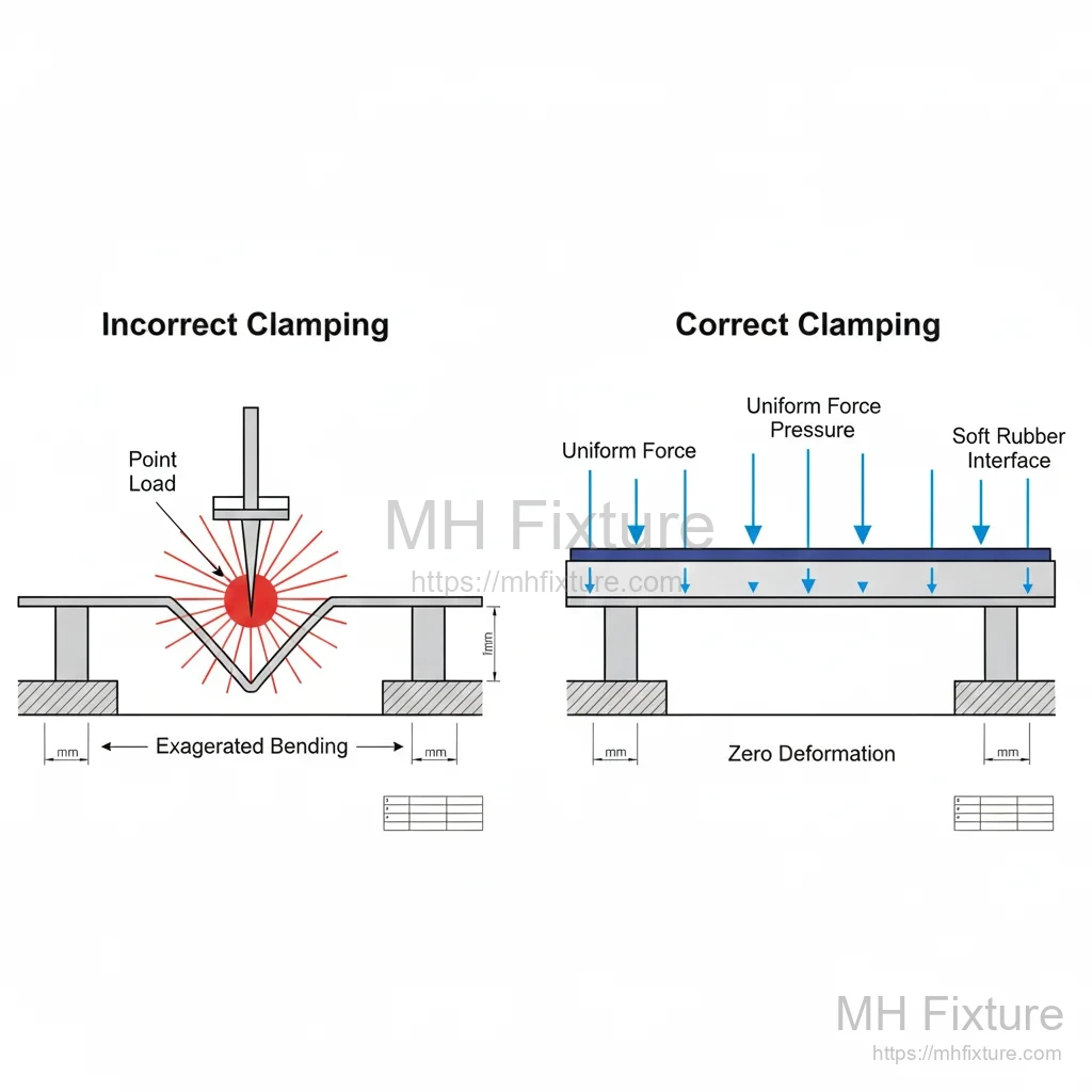
- Pitfalls of Point Contact: Localized concentrated clamping force generates Hertzian contact stress, causing plastic indentation or significant local elastic deformation in the contact zone.
- "Forced Correction" from Over-Constraint: Attempts to increase stiffness by adding support points can, if support heights are inconsistent, force the part onto an incorrect plane under clamping, locking in initial stresses.
3. Four Key Principles for Thin-Walled Part Fixture Design
1. Coaxial Alignment of Locating and Clamping Forces
Clamping force application points must precisely correspond to locators, ensuring that only compressive stress is induced internally, without shear or bending moments.
2. Transition from Point Support to Envelope Support
Maximize support area whenever possible. Employ profiled support blocks or adaptive materials to distribute load over larger surface areas, reducing pressure per unit area.
3. Combined Rigid-Flexible Support Strategy
Primary locating uses rigid supports to ensure positional accuracy, while secondary locating employs floating supports. In the part's stress-free natural state, floating supports contact the part and lock, providing rigidity without altering part posture.
4. In-Sequence Stress Release Principle
For precision parts, adopt a "rough machining – release and re-clamp – finish machining" strategy. In finish machining, the fixture should provide only the minimum clamping force necessary to counteract cutting forces.
4. Common Failure Cases and Improvement Solutions
The following are typical thin-walled fixture design errors corrected in our custom services:
Case 1: Local Collapse Caused by Point Clamping
- Error Description: Aluminum alloy thin-walled cover clamped at edges using standard hold-down plates with point contact.
- Result: 0.05 mm depression at clamp points; after finish milling, clamped areas thicker, surrounding areas thinner.
- Improvement Solution: Implement annular continuous clamping mechanism or pressure bars with elastic pads to distribute point loading into line loading.
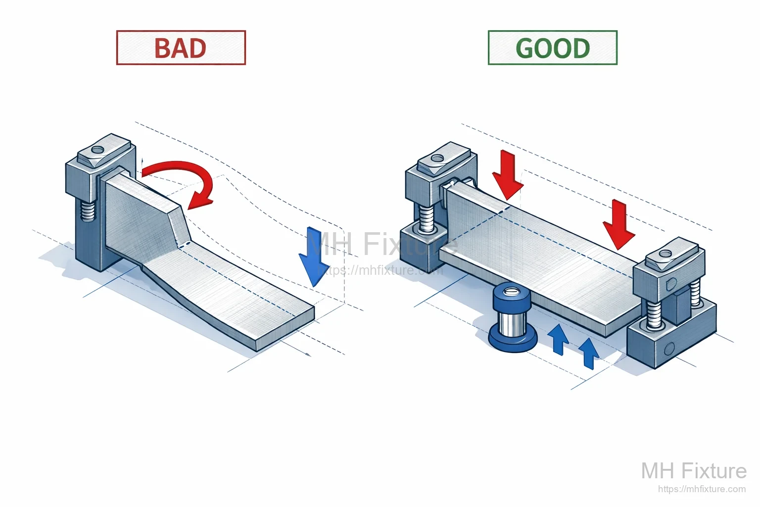
Case 2: Overall Warpage from Unilateral Clamping
- Error Description: L-shaped thin-walled part clamped intensively on one side only to resist cutting forces.
- Result: Cantilever-like overall deformation, leading to out-of-perpendicularity on machined end faces.
- Improvement Solution: Adopt symmetrical balanced clamping with adaptive hydraulic auxiliary supports on non-machined faces.
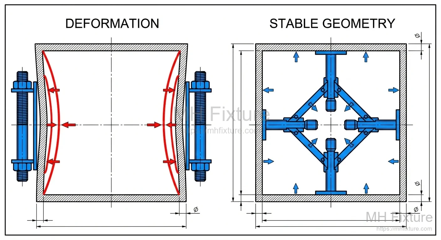
Case 3: "Rigid Locking" of Thin-Walled Box Side Walls
- Error Description: During internal cavity machining, rigid bolts used to jack outward against side walls.
- Result: Side walls slightly contract inward; after cavity machining, walls spring back, resulting in oversized internal dimensions.
- Improvement Solution: Use expanding mandrel locating or low-melting-point alloy fill support to provide outward radial support from inside.
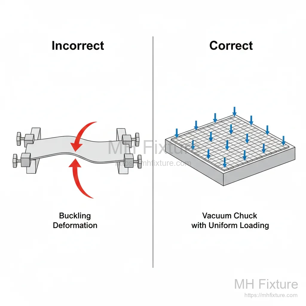
Case 4: Edge Clamping Deformation in Sheet Parts
- Error Description: Thin sheet clamped around perimeter using side-action fixtures.
- Result: Part undergoes buckling instability, with slight central arching.
- Improvement Solution: Employ vacuum fixture to achieve uniformly distributed downward pressure via atmospheric pressure.
5. Engineered Solutions and Mature Approaches
1. Vacuum Fixtures
- Applicability: Ultra-thin flat plates and large-area thin-walled parts.
- Advantages: Extremely uniform pressure distribution with zero induced stress.
- Limitations: Cannot resist strong lateral cutting forces (requires auxiliary rigid side stops).
2. Conformal Supports and Phase-Change Material Fixtures
For irregular thin-walled parts, use low-melting-point alloys (Bi-Sn) or flexible magnetic particle supports. Embed the part, allow solidification to achieve 100% conformal envelope support, significantly suppressing machining vibration.
3. Elastic Clamping Mechanisms
Utilize disc springs or constant-pressure pneumatic cylinders to maintain clamping force below the part's deformation threshold. Combine with high-speed, light-cut machining strategies to compensate for reduced clamping rigidity through efficiency.
6. Summary
Custom fixture design for thin-walled parts is an art of "force balance." As designers, we must consider not only how to securely hold the part but also how to support machining forces in the part's "most comfortable" posture.
Successful thin-walled fixture designs must feature:
- Minimal induced deformation.
- Superior vibration damping capability.
- Precise force transmission paths.
Is your process chain bottlenecked by thin-walled part deformation?
Our engineering team specializes in resolving high-difficulty clamping challenges, offering complete solutions from FEA deformation simulation to high-precision fixture manufacturing. Contact us for your dedicated fixture diagnostic report.