Eliminating Machining Deformation: A Case Study on Axial Clamping Fixture Design for Thin-Walled Shell Parts
Thin-walled tubular and shell parts are highly susceptible to deformation when clamped radially during machining. This article presents a practical fixture design case based on a Morse taper mandrel and axial clamping. By switching between a dual pressure-plate clamping sequence, both internal and external machining operations are completed in a single setup, effectively eliminating clamping-induced deformation and ensuring strict geometric tolerances.
In the field of high-precision component manufacturing—especially when machining thin-walled shell workpieces for connection products—eliminating positioning errors and clamping deformation has always been a significant challenge for engineers.
Typically, the industry leans toward mandrel positioning with multiple setups or using soft jaws for radial clamping. However, for parts with extremely thin walls and strict tolerance requirements, these conventional methods often fall short. This article shares an innovative tooling design to eliminate clamping force deformation by converting "radial force" into "axial force," perfectly resolving the pain points of machining thin-walled shell parts.
1. Case Background: The Challenge of Thin-Walled Shell Parts
We faced a machining project involving a typical thin-walled shell part (as shown below).
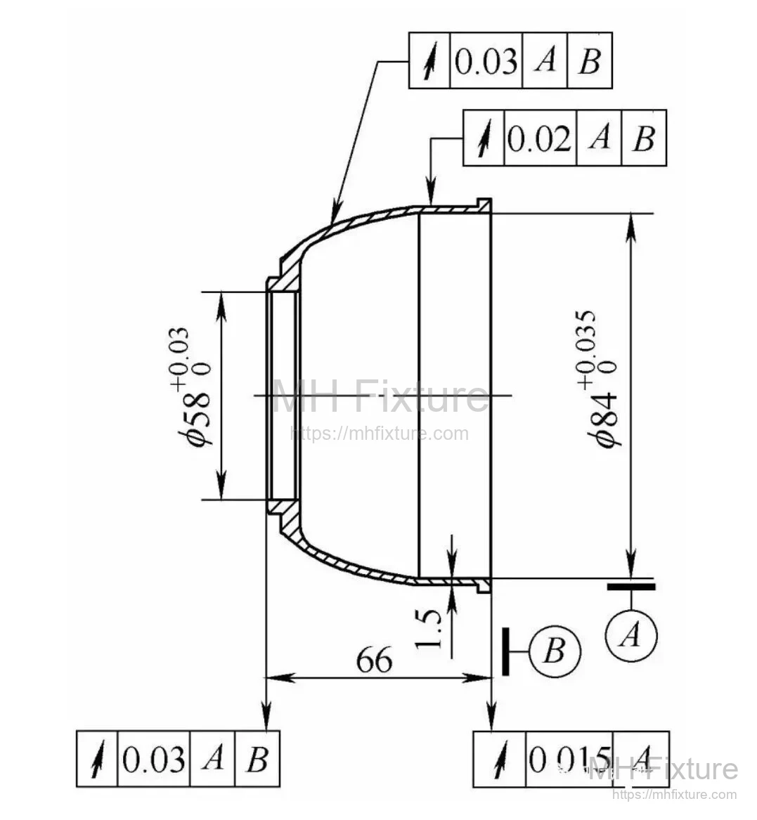
- Part Features: An elliptical curve shape featuring a small end bore (Φ58H7) and a large end bore (Φ84H7).
- Critical Difficulty: The wall thickness is only 1.5mm.
- Precision Requirements: Extremely high geometric tolerance requirements relative to the datum hole face.
Machining Difficulty Analysis: The rigidity of this part is extremely poor, with a diameter-to-length ratio (D/L) ≥ 10. During machining, any radial pressure from tools or fixtures can easily cause elastic deformation. To meet dimensional accuracy, theoretically, machining must be completed in a single setup. However, due to the structure, traditional solutions hit a dead end:
- Split Processes: Turning the outer diameter (OD) and then the curved surface involves re-clamping (secondary setup), making it impossible to guarantee geometric tolerances.
- Soft Jaws: Direct radial clamping of the OD or ID causes the part to deform; once released, "spring-back" leads to out-of-tolerance dimensions.
- Internal Expanding Mandrel: Even with an elastic expanding mandrel, the outward expansion force causes "polygon deformation" due to the extreme thinness of the walls.
2. Solution: Design Principle and Overall Structure
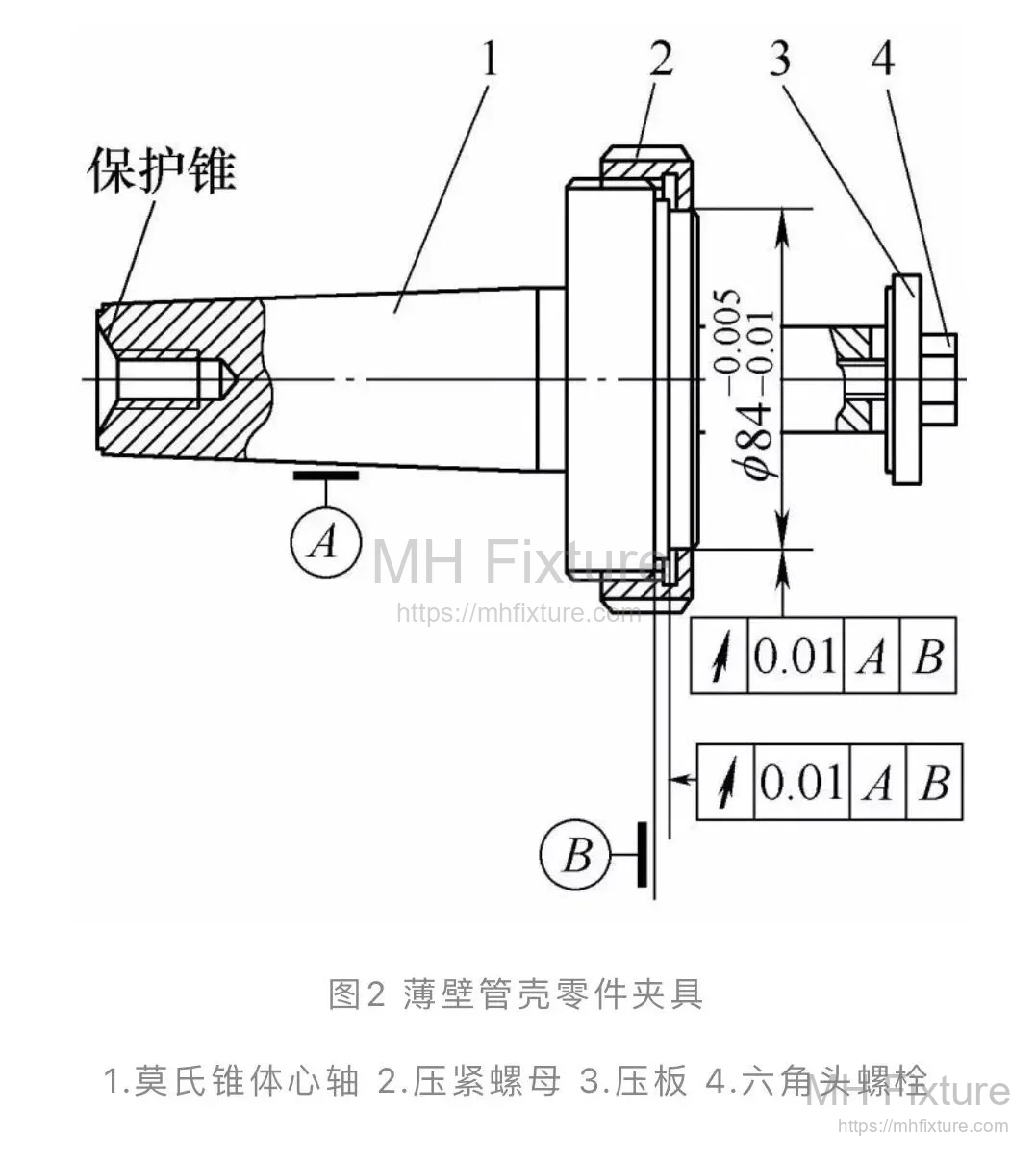
To address these pain points, we designed a dedicated fixture featuring end-face clamping with a dual-plate switching mechanism.
Core Concept: Abandon radial clamping in favor of axial clamping. By centering with a Morse taper mandrel and applying pressure to the end face, the part remains free from radial stress throughout the process, fundamentally overcoming deformation caused by radial forces. If you need customized solutions for special parts, please view our Custom Machining Fixtures.
Overall Fixture Structure: (As shown below) The part is located on a Morse taper mandrel. Through a clever "clamp plate switching" process, the OD, bore, and end face are machined in one go without loosening the part's datum reference.
3. Detailed Fixture Design Analysis
The success of this tooling relies on the coordination of three core components:
(1) Positioning Datum: Morse Taper Mandrel
The main body of the fixture is a Morse taper positioning mandrel (as shown below).

- Connection: Mated to the machine tool spindle bore via a taper fit.
- Advantage: Ensures the fixture's center height is highly consistent with the machine spindle's center of rotation through micro-correction of the fit clearance.
- Precision Control: The positioning clearance of the part on the mandrel is calculated based on error analysis to fully meet machining requirements.
(2) Step 1 Clamping: Special Compression Nut
The compression nut (as shown below) is responsible for the initial fixation of the part.
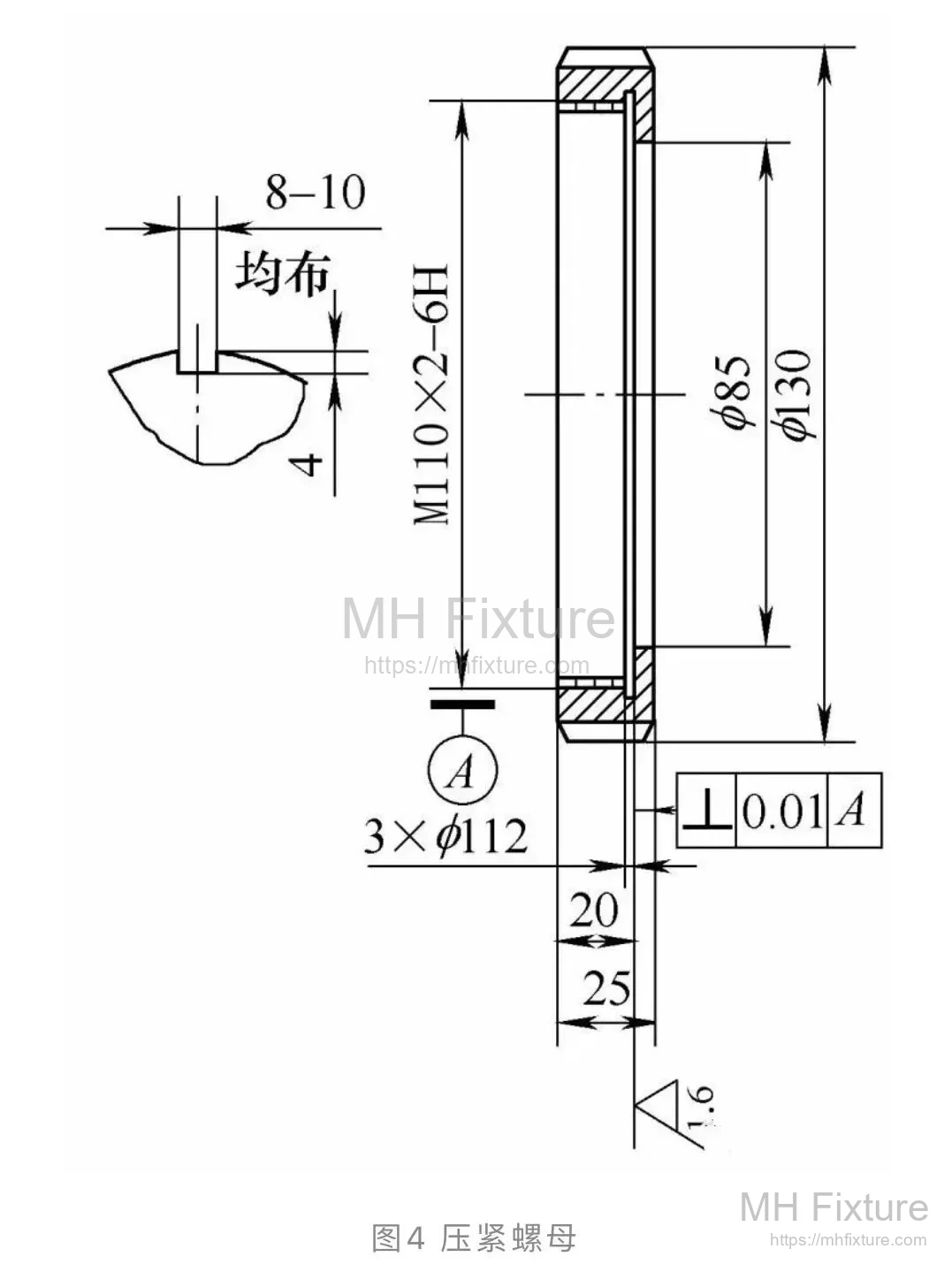
- Operation: After the part is loaded onto the mandrel, the compression nut is tightened. The inner face of the nut presses against the outer step face of the thin-walled part, locking the component axially.
- Force Analysis: The clamping force is transmitted axially, effectively eliminating vibration caused by the main cutting force.
- Machining Scope: In this state, the Φ58H7 small end bore and the end face are machined. Since there is no radial force, there is no rebound deformation after machining.
(3) Step 2 Switching: Process Conversion Clamp Plate
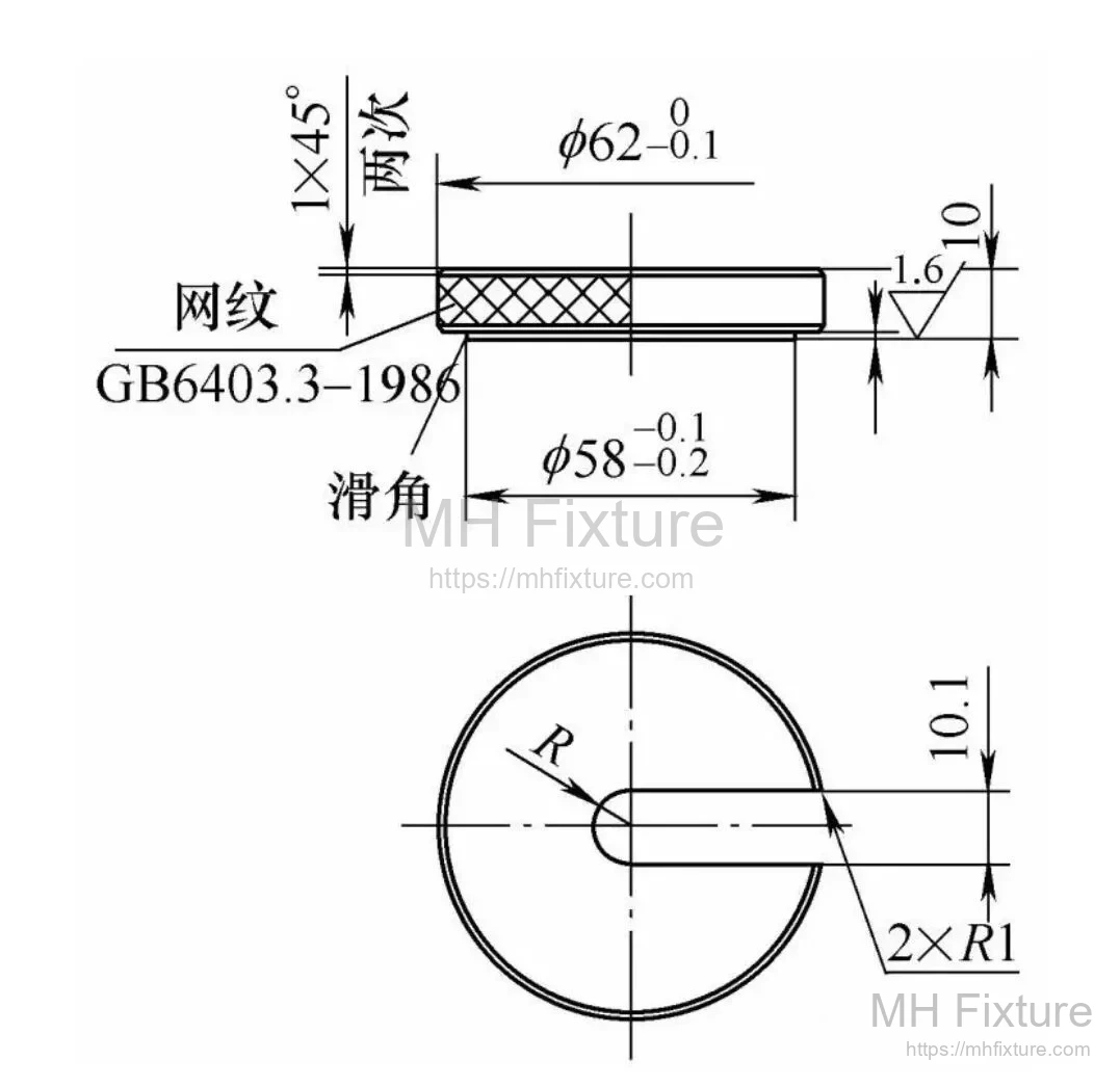
This is the essence of the design. Once the inner bore and end face are machined, the machine stops, but the part is not removed. We then switch to the clamp plate (as shown below).
-
Plate Design:
-
Anti-Slip Feature: The front of the plate features a Φ58mm step (1mm deep). During clamping, this step extends into the newly machined Φ58H7 bore with a clearance fit, preventing the plate from detaching during high-speed rotation.
-
Quick-Change Feature: The plate is designed with a 10.1mm open slot, allowing for rapid installation and removal by slightly loosening the hex bolt.
-
Switching Logic:
- Install the clamp plate, applying axial clamping force to the face of the Φ58H7 bore (Secondary Clamping).
- At this point, the part is secured by the plate, and its position remains unchanged.
- Using the wrench slot on the compression nut, quickly remove the initial compression nut.
-
Machining Scope: With the nut removed, the outer diameter of the part is exposed, allowing for the completion of the remaining profile machining.
4. Summary and Results
Through this "relay-style" clamping method, the thin-walled shell part benefits throughout the entire machining cycle:
- Zero Radial Clamping Force: Physical deformation is eliminated from start to finish.
- Maintained Single Positioning Datum: Errors from secondary setups are eliminated.
- Stable Axial Clamping: Effectively suppresses cutting vibrations common in thin-walled parts.
Conclusion: This tooling has been validated in actual production with excellent results, perfectly guaranteeing the dimensional precision and geometric tolerances of the thin-walled shell parts. This design approach—utilizing the part's own structural features for "dual-plate axial clamping"—not only solves current machining difficulties but is also highly suitable for application in other similar thin-walled or precision connection components.
This article is curated and shared by the MH Fixture Technical Team. For more fixture design examples, please refer to our case studies. We specialize in providing professional tooling and fixture solutions for you.