Designing Multi-Functional Inspection Gauges for Vacuum-Formed Refrigerator Liners
Measuring complex vacuum-formed parts with calipers often leads to inconsistency and high cycle times. This case study details the design of a multi-functional "Go/No-Go" step gauge for refrigerator liners. The solution reduces inspection time by 75% while strictly controlling critical interface dimensions.
The Challenge: Dimensional Stability in Thermoforming
The vacuum-formed inner liner is a critical structural component in refrigerator assembly. Its dimensional accuracy directly impacts the final aesthetic quality, insulation performance, and the fit of internal shelving. However, due to the material characteristics of thermoformed plastics (typically ABS or HIPS), controlling shrinkage and deformation is a persistent engineering challenge.
Specifically, the following Critical-to-Quality (CTQ) features require strict control:
- Light Box Step Height: Ensures proper seating of lighting modules.
- Liner Edge Step: Critical for the interface between the liner and the outer shell.
- Sealing Flange Width: Essential for foam leakage prevention.
- Corner Flatness: The 24-sided geometry must align perfectly with the cabinet.
In legacy quality control processes, operators relied on handheld calipers and subjective visual inspection. This approach presented significant issues:
- High Measurement Variation: Caliper pressure varies by operator, deforming soft plastic parts.
- Low Efficiency: Measuring multiple complex points manually is time-consuming.
- Data Inconsistency: Lack of a standardized reference datum led to false passes or false rejects.
To address these issues, the technical team developed a specialized inspection fixture solution to transition from variable measurement (calipers) to attribute gauging (functional checks).
Engineering Solution: The Multi-Functional Step Gauge
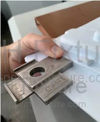
To standardize the inspection process, a custom "Go/No-Go" block gauge was designed. This tool integrates four specific dimensional standards into a single, hardened tool steel block, prioritized for ergonomics and rapid decision-making.
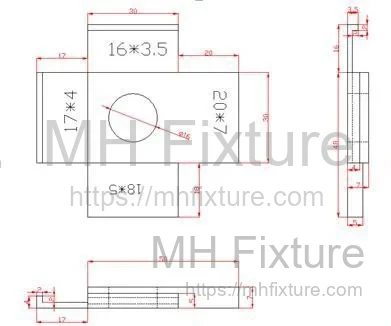
Liner Inspection Gauge Design Schematic:
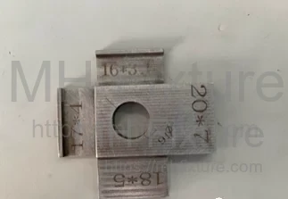
Fabricated Gauge Overview:
Technical Specifications and Usage Definition
The gauge is machined to precise tolerances to represent the nominal dimension minus the allowable tolerance limit (or mating condition). The block features four distinct measuring sides:
1. Dimension A: 30 × 16 × 3.5 mm
- Target Feature: Liner edge conductive strip step height; Generic liner edge width.
- Application: Verifies the step height for legacy light box designs (Models B10129, C0435).
2. Dimension B: 30 × 17 × 4 mm
- Target Feature: Mating interface between the liner edge and the refrigerator cabinet shell.
- Application: Ensures the gap falls within the specified assembly tolerance.
3. Dimension C: 30 × 18 × 5 mm
- Target Feature: Maximum limit width for cabinet mating; Side-suction light box steps.
- Application: Used for models C1315 and C1725 to verify the upper tolerance limit.
4. Dimension D: 30 × 20 × 7 mm
- Target Feature: Standard light box step height.
- Application: Primary verification for models B15189, B17123, B15175, and B1528.
Operational Methodology: Standardized Inspection Logic
The gauge is designed to simplify complex metrology into three distinct actions, eliminating the need for operators to read vernier scales.
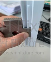
- Action 1: The "Slot" Check (Mating Verification)
- Method: Insert the gauge (Side 1 or 2) into the liner's self-locking step.
- Criteria: The gauge surface must sit flush with the liner surface. Gaps or rocking indicate the step height is out of tolerance.
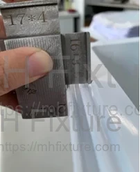
- Action 2: The "Vertical" Check (Width Verification)
- Method: Place the gauge upright against the liner edge step (Side 1 or 2).
- Criteria: The gauge acts as a width template. If the liner edge extends beyond or falls significantly short of the gauge width, the part is rejected.
- Action 3: The "Abutment" Check (Height/Flatness)
- Method: Lean the gauge (Side 3 or 4) against the light box step.
- Criteria: Check for daylight between the gauge and the step surface. This confirms the planar flatness and step height simultaneously.
Implementation Results: Lean Manufacturing Efficiency
The introduction of this dedicated gauging system has transformed the quality control process on the production line.
-
Cycle Time Reduction: A complete inspection of a single liner involves checking 22 distinct points.
- Previous Method (Calipers): ~4 minutes per unit (measurement + reading + recording).
- Current Method (Step Gauge): <1 minute per unit.
- Result: A 75% reduction in inspection time, significantly reducing production bottlenecks.
-
Process Capability Improvement: By removing the variability of caliper usage, the measurement system analysis (MSA) shows higher reproducibility. Operators now capture images of the gauge in the "No-Go" position for the first-piece inspection, creating a verifiable digital audit trail.
-
Waste Reduction: Following Lean principles, this tool eliminates the waste of "excess motion" and "waiting." The immediate feedback loop allows for faster machine adjustments, reducing scrap rates during startup.
Conclusion
Small-scale tooling improvements often yield the highest return on investment in mass production. By replacing general-purpose measuring tools with custom-engineered functional gauges, manufacturers can achieve tighter tolerance control and higher throughput.
For more information on custom metrology solutions and checking fixtures, please visit our Specialized Inspection Fixtures category.