Fixture Design for Irregular Castings: 3 Engineering Case Studies
Machining irregular cast parts often leads to low OEE due to complex setup requirements and clamping deformation. This engineering case study analyzes three custom hydraulic fixture designs—including split-cavity jaws and Poka-Yoke mechanisms—that significantly reduce setup time and ensure process stability.
Abstract
In the machining of cast products, traditional clamping methods using right-angle plates and V-blocks often result in low efficiency and process variability. There is a scarcity of technical literature addressing specific fixture designs for irregular turning parts. This article summarizes advanced design methodologies for irregular components—specifically valve bodies and automotive flanges—based on extensive manufacturing engineering experience. These cases provide a reference for optimizing custom hydraulic fixture solutions to improve Overall Equipment Effectiveness (OEE).
1. Introduction
To maximize OEE in CNC machining, manufacturing engineers prioritize the reduction of setup times through advanced tooling strategies. While mold making utilizes quick-change systems and automated handling, turning operations for irregular castings often lag behind. Replacing manual clamping with hydraulic self-centering chucks or custom two-jaw systems is critical for minimizing non-cutting time and ensuring repeatability in precision CNC fixture design.
2. Case Study: Split-Cavity Fixture for Valve Bodies
2.1 Engineering Challenge
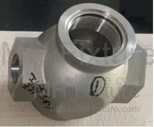
The component is a "wide-body" valve housing (Figure 1) requiring a top bore of _φ_42.86mm and 1-3/4-16UN-2B threading.
- Process flow: Turn the top inner bore; locate via the bore; rotate 180° to turn threads on both ends.
- Traditional Approach: A faceplate with V-blocks and strap clamps.
- Defects: This method prohibits the use of standard hydraulic chucks, extends changeover time, requires static balancing, and limits RPM, thus reducing productivity.
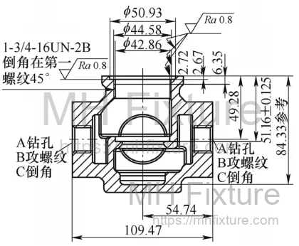 a)Plan View
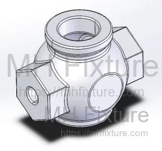 b)3D Raw Casting
2.2 Design Optimization
The improved design utilizes a hydraulic two-jaw chuck or self-centering chuck based on the six-point location principle.
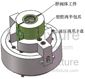
- Locating Scheme: The green sections (Figure 2) serve as the V-block equivalent locating surfaces.
- Interference Avoidance: The red sections are relieved by 2–3mm to accommodate casting flash and irregularities.

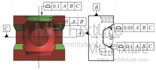
2.3 Implementation
The hydraulic clamping configuration (Figures 4 and 5) ensures rigid holding.
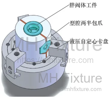
2.4 Manufacturing Specs
- Material: AISI 1045 (45# Steel), Quenched and Tempered to 28–32 HRC.
- Split Design: Designed similarly to a split mold cavity with a 3–5mm gap between jaws.
- Tolerance Control: The external profile and V-location center are controlled within 0.1mm relative to the hex ends.
- Clearance: Non-locating surfaces have a 2–3mm relief to handle casting tolerances.
2.5 Results
- Process: Wire EDM splitting -> Cavity machining -> Deburring.
- Efficiency: Setup time reduced by >45% compared to manual V-blocks.
- Performance: Clamping rigidity allowed for aggressive cutting parameters, increasing overall efficiency by 105%.
3. Case Study: Poka-Yoke Hydraulic Fixture for Automotive Flanges
3.1 Component Analysis
The part is an automotive exhaust flange (Figure 7) with a specific 1.5° draft angle.
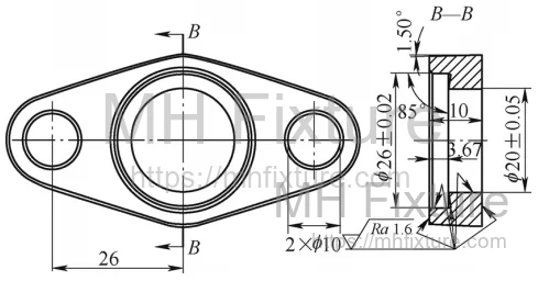 a)Plan View
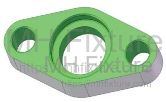 b)3D View
3.2 The Problem
The previous process involved magnetic clamping for face milling, followed by turning. Crucially, the process ignored the 1.5° draft angle direction. Without error-proofing (Poka-Yoke), 60% of parts were machined in reverse orientation, causing severe customer rejections.
3.3 Solution: Integrated Mistake-Proofing
The process was redesigned to use a dedicated hydraulic fixture on a machining center (Figure 8).
- Draft Angle Identification: A visual marker was added to the raw casting mold.
- Fixture Design: The fixture jaws profile was machined with a matching 1.5° inverse draft. If the part is loaded incorrectly, the angles do not mate, and the part cannot be clamped securely.
- Process Consolidation: Face milling and boring were combined into a single setup.
 1—Jaw Body, 2—Flange Workpiece, 3—Fixed Profile Plate, 4—Chuck/Soft Jaw
3.4 Fabrication & Results
- Fabrication: Soft jaws are mounted, and profile plates are welded. The internal profile is machined with the 1.5° draft angle.
- Safety: The interlocking draft angles act as a dovetail, preventing the workpiece from being dislodged by centrifugal forces (Clamping force adjusted to 5–10kg/mm).
- Outcome: Eliminated reverse-loading defects entirely. Overall efficiency increased by 60% due to process consolidation.
4. Case Study: Self-Centering Fixture for Precision Cast Elbows
4.1 Challenge
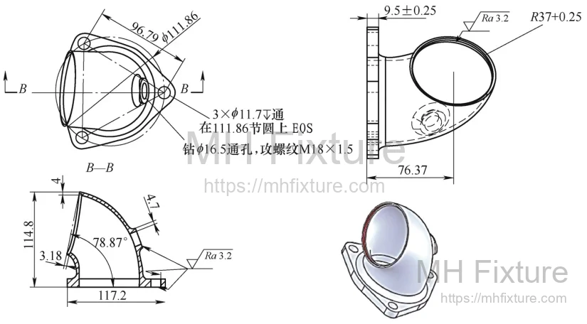
A precision cast elbow (Figure 9) was previously machined using split block molds on a VMC table.
- Cycle Time: 4 minutes for setup.
- Issues: Casting deformation caused poor positioning accuracy in the fixed square blocks.
4.2 Design Improvements
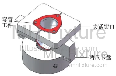
The new strategy uses a converted two-jaw chuck for milling (Figure 10).
4.3 Fabrication Process
- Material: AISI 1045, 28–32 HRC.
- Procedure: Profile plates are welded to standard soft jaws.
- Calibration: The jaws are bored/milled in place on the machine to ensure concentricity.
- Separation: A 4–6mm slot is milled through the center to separate the jaws, creating a self-centering mechanism.
4.4 Operational Gains
- Setup Time: Reduced from 4 minutes to 30 seconds (+700% improvement).
- Cycle Time: Reduced from 8 minutes to 3 minutes due to higher rigidity.
- Total Efficiency: +167% improvement.
5. Critical Considerations for Large-Stroke Casting Fixtures
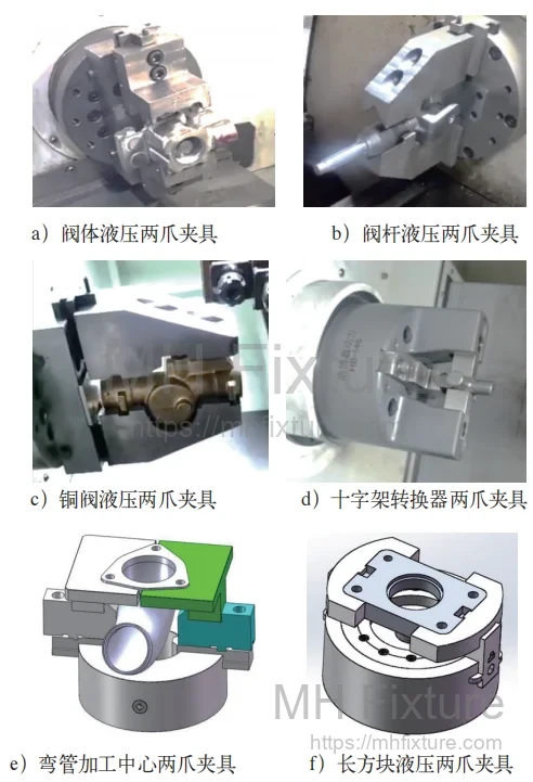
When designing fixtures for large casting shells (Figure 11), the following engineering principles must be observed:
- Avoid Over-Constraint: Strictly adhere to the six-point location principle. Use V-blocks for cylindrical sections and ensure adequate clearance for non-functional surfaces to prevent interference.
- Clamping Deformation: Castings are prone to deformation. Design clamping forces and locations to minimize distortion while maintaining sufficient grip for roughing cuts.
- Material Selection: Use AISI 1045 (or equivalent) for jaw bodies. For high-volume production, consider heat treatment and wire EDM for precision profiles.
- Auxiliary Support: For heavy cuts, incorporate carbide grippers or auxiliary supports (Figure 12) to enhance friction and safety.

6. Conclusion
The transition from manual, general-purpose clamping to dedicated hydraulic fixture design is essential for modern manufacturing competitiveness. As demonstrated by these cases, correctly implemented split-mold jaws and mistake-proofing mechanisms can drastically improve OEE.
For manufacturers seeking to upgrade their production capabilities with high-precision workholding, explore our fixture solutions to achieve superior process stability and efficiency.