Eccentric Fixture Design Strategies for Precision Crankshaft Machining
Machining eccentric parts like crankshafts often leads to clamping instability and low efficiency. This article details advanced hydraulic fixture designs—including wedge-driven systems and hydraulic expansion arbors—that solve radial positioning challenges. These solutions significantly reduce setup time and ensure concentricity within strict engineering tolerances.
In mechanical transmission systems, eccentric shafts and crankshafts are fundamental components used to convert rotary motion into reciprocating motion. Despite their widespread application, machining eccentric parts remains a process challenge due to the difficulty in controlling positioning accuracy, eccentricity tolerances, and clamping stability.
This article explores advanced hydraulic clamping fixtures designed to resolve these engineering challenges, focusing on solutions for turning and grinding operations.
1. Hydraulic Automatic Eccentric Fixture Design for Crankshaft Turning
The crankshaft is a critical component in automotive and internal combustion engines. Its machining accuracy directly impacts engine performance. Traditional manufacturing often relies on manual eccentric fixtures (see Figure 1), which suffer from low clamping force, high labor intensity, and safety risks.
 1-Front Pressure Plate 2-Rear Pressure Plate 3,4-Screws
1.1 The Wedge-Driven Hydraulic Solution
To overcome manual limitations, a novel Hydraulic Automatic Eccentric Fixture has been developed (see Figure 2). This design utilizes a fixed-eccentricity, single-jaw floating clamping mechanism.
Key Design Features:
- Power Transmission: A rotary hydraulic cylinder provides the actuation force.
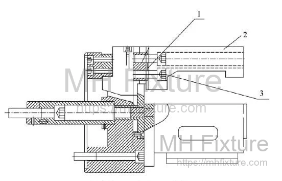
- Force Conversion: An internal wedge mechanism converts axial hydraulic force into radial clamping force.
- Dual-Speed Action: The internal wedge features a dual-angle profile (45° at the front, 15° at the rear). This allows for rapid approach (fast feed) followed by high-force, low-speed clamping as the jaw engages the workpiece.
- Synchronization: Installed on both the headstock and tailstock (or opposing spindles), the fixtures synchronize to clamp the workpiece simultaneously.
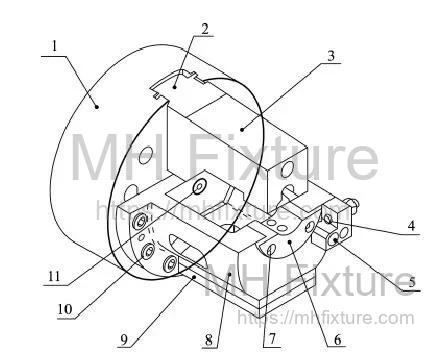 1-Fixture Base 2-Jaw Slide 3-Jaw 4-Adjustment Screw 5-Angular Locator 6-Semi-cylindrical Pad
7,10-Screws 8-Fixture Body 9-Counterweight 11-Dowel Pin 12-Machine Spindle Nose
1-Fixture Base 2-Jaw Slide 3-Jaw 4-Adjustment Screw 5-Angular Locator 6-Semi-cylindrical Pad
7,10-Screws 8-Fixture Body 9-Counterweight 11-Dowel Pin 12-Machine Spindle Nose
1.2 Structural Engineering and Alignment
- Mounting & Positioning: The fixture base (1) connects to the machine spindle nose (12). The fixture body (8) is located via dowel pins (11) and secured with high-strength screws. The distance between the dowel pin center (spindle rotation axis) and the semi-cylindrical pad (6) center defines the specific eccentricity offset.
- Eccentricity Adjustment: The semi-cylindrical pad (6) acts as the primary radial locator. Its inner arc and the flange face are scraped/mated to precisely control the eccentricity and axial deviation.
- Angular Orientation: An angular locator (5) ensures the crankshaft journals align relative to the reference plane.
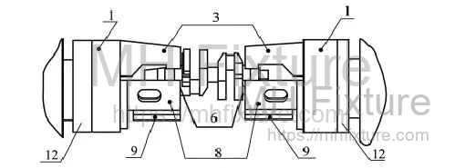
- Clamping Mechanism: The jaw slide moves radially within a guide slot. Driven by the internal wedge's axial movement, the jaw secures the workpiece against the static locators.
1.3 Operational Advantages
Comparative studies verify significant efficiency gains with this design:
- Cycle Time Reduction: Manual fixture loading takes ~1.5 minutes; the hydraulic system reduces this to ~10 seconds. Unloading time drops from 40 seconds to 8 seconds.
- Process Capability: The high-force hydraulic clamping minimizes workpiece deformation, significantly improving dimensional stability and surface finish.
2. Hydraulic Expansion Fixture for Crankshaft Grinding
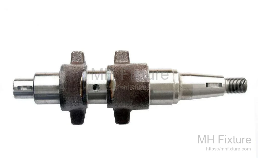
Grinding the connecting rod journal of a crankshaft requires extreme precision. For components like vehicle air compressor crankshafts (Figure 5), the grinding process dictates the final torque transmission efficiency.
Standard grinding workflows (Figure 6) often face challenges with concentricity when using conventional chucks.

2.1 Hydraulic Expansion Arbor System
The improved solution utilizes a Hydraulic Expansion Fixture system powered by a rotary union and hollow spindle architecture.
System Composition:
- Rotary Hydraulic Cylinder: Mounted at the rear of the spindle.
- Fluid Transmission: High-pressure hydraulic oil is routed through the hollow spindle via hoses to the fixture body.
- Expansion Mechanism: The core innovation involves a thin-walled sleeve (diaphragm or hydro-sleeve) that expands elastically under oil pressure to clamp the workpiece.
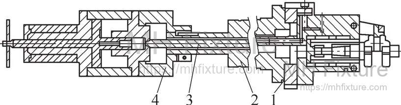 1-Eccentric Fixture 2-Headstock Spindle 3-High-Pressure Hose 4-Rotary Hydraulic Cylinder
2.2 Hydraulic Circuit Logic
The rotary cylinder (Figure 8) uses a pressure-intensification circuit.
- Loading: Hydraulic oil enters the large cylinder chamber, moving the piston.
- Clamping: Oil flows through a check valve into the thin-walled sleeve's annular chamber.
- Pressure Maintenance: The check valve prevents backflow, ensuring the sleeve maintains constant pressure on the workpiece. This eliminates "breathing" or loosening during the grinding cycle.
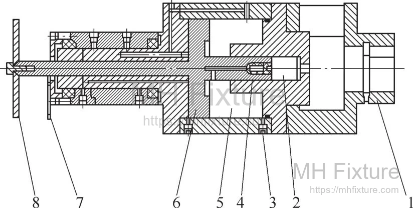 1-Flange 2-Small Cylinder 3-Bleed Screw 4-Check Valve 5-Large Cylinder
6-Piston 7-Sensor Bracket 8-Signal Plate
1-Flange 2-Small Cylinder 3-Bleed Screw 4-Check Valve 5-Large Cylinder
6-Piston 7-Sensor Bracket 8-Signal Plate
2.3 Fixture Body Design
The fixture body (Figure 9) includes a V-block locator (1) for initial self-centering.
- Process: The operator loads the crankshaft into the elastic sleeve (4). The V-block is manually engaged to align the journal axis with the spindle axis.
- Actuation: Once aligned, hydraulic pressure expands the sleeve to clamp the part. The V-block is then retracted to prevent interference with the grinding wheel.
- Balancing: Integrated counterweights (7) are adjusted to align the center of gravity with the spindle axis, preventing vibration at high rotational speeds.
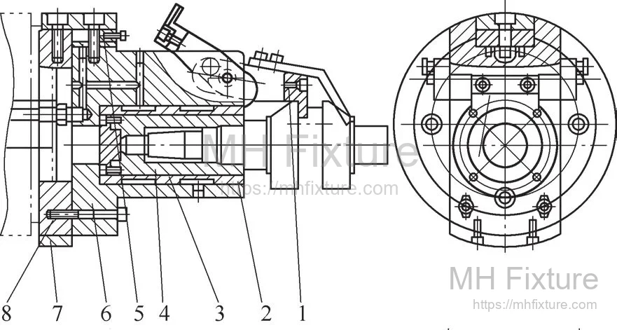 1-V-Block Locator 2-Axial Positioning Plate 3-Thin-Walled Sleeve 4-Elastic Sleeve 5-Adjustment Shim
6-Fixture Body 7-Counterweight 8-Connection Plate
1-V-Block Locator 2-Axial Positioning Plate 3-Thin-Walled Sleeve 4-Elastic Sleeve 5-Adjustment Shim
6-Fixture Body 7-Counterweight 8-Connection Plate
This design serves as a robust foundation for precision grinding jigs, enabling high-precision finishing of complex eccentric geometries.
3. Modified Self-Centering Chuck for Eccentric Turning
For low-volume production or prototyping, dedicated hydraulic fixtures may be cost-prohibitive. A cost-effective alternative involves modifying a standard three-jaw self-centering scroll chuck to accommodate eccentric offsets.
3.1 Standard Chuck Mechanics
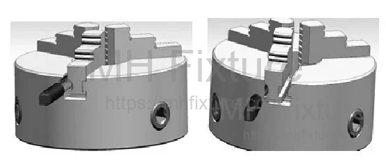
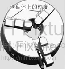
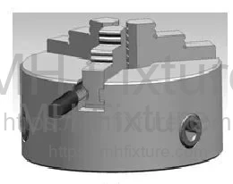
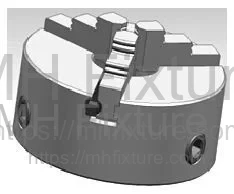
In a standard scroll chuck (Figure 10), rotating the pinion gear drives the scroll plate (large bevel gear), which moves all three jaws simultaneously towards the center.

3.2 The Offset Modification Strategy
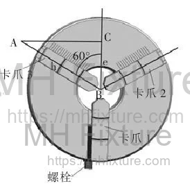
To achieve a specific eccentricity () without complex fixtures, one jaw (Jaw 1) can be modified (Figure 11) to allow independent disengagement from the scroll thread.
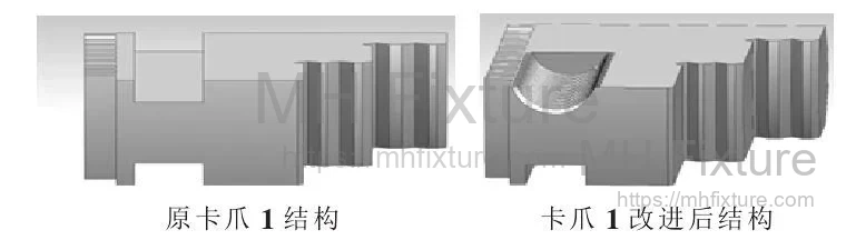
Operational Procedure:
- Disengage: Loosen the bolt on Jaw 1 to disengage it from the scroll plate. Jaws 2 and 3 remain engaged.
- Offset Adjustment: Rotate the chuck key. Jaws 2 and 3 will move, creating an off-center pocket.
- Re-engage: Once the correct offset is achieved, re-engage Jaw 1 with the scroll thread.
- Clamp: Tightening the chuck now clamps the part in an eccentric position.
3.3 Calculating the Offset
The relationship between the jaw movement () and the required eccentricity () is derived from the geometry of the 120° jaw arrangement (Figure 16).
Therefore, to achieve an eccentricity of , Jaws 2 and 3 must be displaced by a distance of .
3.4 Engineering Case Study
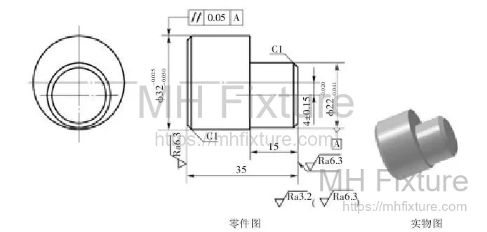
Task: Machine a component from stock with an eccentricity (Figure 17).
Process:
- Calculate Displacement: .
- Setup: Disengage Jaw 1. Rotate the scroll to move Jaws 2 and 3 inward by 8mm.
- Secure: Re-engage Jaw 1 and clamp the workpiece.
- Machining: Perform turning operations on the eccentric section ( axis).
Conclusion
Whether employing high-volume hydraulic expansion systems or modified chuck strategies for prototyping, selecting the correct eccentric clamping method is vital for process stability. These engineered solutions eliminate the trial-and-error of manual alignment, ensuring repeatable tolerance adherence in industrial manufacturing.
For specialized advice on complex workholding challenges, explore our custom fixture solutions.