End Cover Eccentric Hole Turning: Custom Lathe Fixture Design
Traditional milling of eccentric holes on end covers often results in low efficiency and complex setups. This technical article presents a dedicated horizontal lathe fixture utilizing precise multi-surface location and dynamic counterbalancing to align the eccentric axis. The design enables single-setup turning and chamfering, ensuring ±0.1 mm eccentricity tolerance and high production rates.
1. Introduction
Eccentric components are widely utilized in mechanical equipment assemblies. The simplicity and efficiency of the chosen machining process directly impact the final dimensional accuracy and overall production yield of the workpiece. Conventional machining strategies typically rely on vertical milling or horizontal boring centers to process eccentric features. However, these methods involve complex operational workflows, extended cycle times, and high demands on operator proficiency. Consequently, they are ill-suited for high-volume production and struggle to meet modern manufacturing efficiency requirements.
To resolve these bottlenecks, optimizing the production of such components requires robust precision machining fixtures that overcome the inefficiencies of traditional methods. This article details the design of a specialized machining fixture for a horizontal lathe, specifically engineered for turning the eccentric hole of an outer shell end cover. This fixture eliminates the complex operations, long cycle times, and precision instability associated with legacy methods. By offering straightforward, accurate location and user-friendly operation, the fixture lowers operator skill requirements while guaranteeing dimensional accuracy, fully satisfying the demands of mass production.
2. Workpiece Process Analysis
As illustrated in Figure 1, the workpiece is an outer shell end cover. The raw blank material is QT450 (nodular cast iron). The eccentric hole to be machined has a diameter of ø30 mm, an eccentricity offset of 8±0.1 mm, a face chamfer of 0.5 mm × 45°, and a surface roughness requirement of Ra 3.2 μm, indicating relatively high precision requirements.
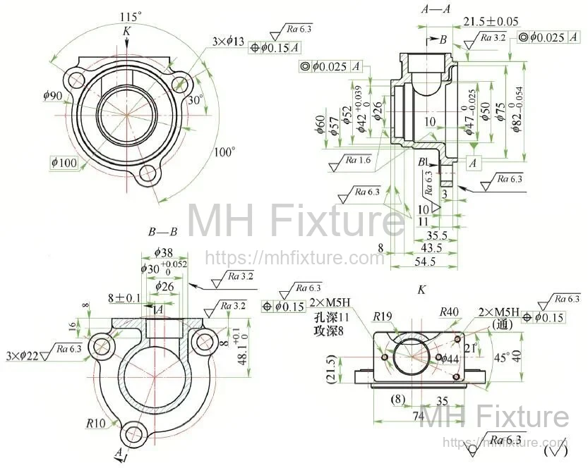
If processed using traditional boring mill methods, the eccentric hole machining must be followed by tool changes, tool offsetting, and repositioning to machine the face chamfer. This extended workflow not only increases cycle time but also introduces setup inconsistency.
To improve precision and lower production costs, a dedicated horizontal lathe fixture was designed. By utilizing custom lathe fixtures to align the eccentric hole's theoretical axis directly with the lathe spindle's axis of rotation, the operation transitions to a standard turning process. The lathe spindle provides the primary rotational motion, while the turning tool provides linear axial feed. Once the bore is turned, a simple tool change allows for immediate face chamfering without re-clamping. This single-setup approach eliminates repositioning errors, reduces cycle time, and significantly boosts production efficiency.
3. Fixture Design Requirements
Given the strict precision requirements for the eccentric hole and the necessity of single-setup chamfering, the fixture must provide highly accurate location capabilities. During the engineering phase, the following critical factors were addressed:
- (1) Dynamic Balancing and Clamping: Shifting the workpiece off-center to align the eccentric bore with the spindle creates an uneven mass distribution. During high-speed rotation, this generates substantial centrifugal forces, which can degrade machining precision, impact surface finish, and create severe safety hazards. Therefore, a counterweight must be integrated into the fixture base. Based on the workpiece mass, a preliminary counterweight of 3 kg is designated, which is subject to dynamic fine-tuning during trial runs.
- (2) Location and Clamping Force: The accuracy of the location directly dictates the final geometric tolerances of the workpiece. The locating datum surfaces must be previously machined features that allow unobstructed tool access to the eccentric hole. The clamping force must be carefully calibrated: excessive force will induce part distortion and surface damage, while insufficient force can lead to part slippage, scrap, and operator danger.
- (3) Mounting and Spindle Interface: To minimize accumulated tolerance stack-up, the number of interface layers between the fixture and the spindle should be minimized. The fixture should ideally mount as directly to the spindle as possible, utilizing a straightforward and rigid connection interface for fast changeovers.
4. Overall Assembly Design
The overall assembly of the dedicated lathe fixture for the end cover is shown in Figure 2. The primary structural components include the locating shaft, vertical base, transition plate, and counterweight block.
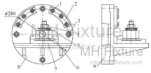
1—Bolt; 2—Counterweight; 3—Hex socket bolt; 4—Nut; 5—Compression spring washer; 6—Workpiece; 7—Locating shaft; 8—Base; 9—Transition plate
The fixture mounts to the lathe spindle via the transition plate. The locating shaft is permanently welded to the vertical base and mates with the workpiece's datum surfaces to ensure exact positioning. To facilitate rapid loading and unloading, the top of the locating shaft is threaded and utilizes a compression spring washer and nut to secure the workpiece.
The vertical base accommodates the counterweight block, counteracting the centrifugal forces generated by the offset mass. This block is bolted to the transition plate for easy adjustment or removal. Crucially, the fixture requires rigorous dynamic balancing during setup. The mass and radial position of the counterweight must be calibrated until the assembly rotates smoothly, neutralizing vibrations and preserving dimensional accuracy.
5. Key Component Design
5.1 Locating Shaft Design
Prior to this operation, the workpiece's internal bores (ø42 mm and ø26 mm) and its outer cylindrical surface (ø82 mm) have already been machined. Following the principle of datum coincidence, these three features are utilized as the locating datums. The custom locating shaft is illustrated in Figure 3.
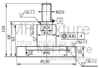
The shaft employs a hole-basis system at the top end to mate with the internal bores, and a shaft-basis system at the bottom where the vertical base's inner bore mates with the workpiece's outer diameter. This dual-end constraint effectively limits the necessary degrees of freedom. The specific dimensional fits are:
- Upper shaft to ø42 mm bore: ø42H7/h6
- Middle shaft to ø26 mm bore: ø26H7/g6
- Base internal register to ø82 mm OD: ø82F8/h7
The locating shaft demands high manufacturing precision, requiring a coaxiality tolerance of ø0.02 mm. The top features an M20×35 mm thread for part clamping.
5.2 Vertical Base Design
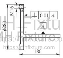
As shown in Figure 4, the vertical base serves as the critical structural link between the locating mechanism and the spindle adapter. To ensure strict perpendicularity between the locating shaft mounting surface and the spindle rotation plane, the base is machined from a single monolithic billet. It features threaded holes at the periphery to allow modular attachment of counterweights. It bolts directly to the transition plate.
5.3 Transition Plate Design
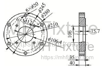
The fixture is deployed on a standard CA6140 horizontal lathe. To ensure rigid and repeatable mounting, the transition plate (adapter backplate) utilizes a short taper and face contact alignment, secured by bolts. The spigot fit between the transition plate and the vertical base is ø210H7/h6. The coaxiality tolerance between the fixture's locating pitch circle and the rotary axis is specified at ø0.01 mm. The internal taper mating with the CA6140 spindle is ø106.4 mm with a taper angle of 7°7'30", as shown in Figure 5.
6. Conclusion
To overcome the manufacturing challenges of eccentric features on cast iron end covers, a dedicated horizontal lathe fixture was engineered and deployed. Production validation demonstrates that turning eccentric holes with this specialized tooling consistently yields dimensions strictly within the required tolerance bands. The system provides rigid multi-surface location, high process stability, and rapid cycle times perfectly suited for mass production environments. Furthermore, by simply swapping the locating shaft, the core fixture assembly offers high modularity for machining various other eccentric cover plates.
For more information on standardizing your production and overcoming complex workholding challenges, explore our custom fixture engineering solutions.