Precision Machining Process Control for Automotive Engine Cylinder Blocks
The machining quality of automotive engine blocks depends critically on process stability across the top deck, cylinder bores, and crankshaft bores. This article details the manufacturing engineering controls, including datum management, **hydraulic clamping fixture** design, and CBN tooling strategies required to achieve micron-level geometric tolerances.
The cylinder block is the foundational structure of an internal combustion engine. Its manufacturing quality directly dictates the engine's power output, fuel efficiency, and longevity. The primary engineering challenge lies in maintaining strict geometric tolerances—specifically flatness, cylindricity, and coaxiality—across three critical zones: the cylinder block top deck, the cylinder bores, and the crankshaft main bearing bores.
Achieving these specifications requires a synergistic approach involving rigid CNC Machining Fixtures, thermal stability control, and advanced cutting tool materials.
1. Technical Specifications and Geometric Tolerances
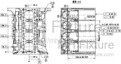
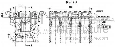
To illustrate the precision required in modern automotive manufacturing, we analyze the critical dimensions of a standard passenger car engine block. The following diagrams define the finished product requirements.
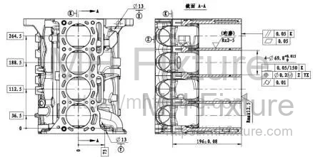
Top Deck Specifications:
- Distance to Crankshaft Bore: Tolerance range of 0.08 mm.
- Surface Roughness: Maximum roughness () of 12.5 μm.
- Parallelism: 0.05 mm relative to the crankshaft bore axis.
- Flatness: 0.05 mm across the entire sealing surface.
Cylinder Bore Specifications:
- Diameter Tolerance: 0 to +0.015 mm.
- Perpendicularity: 0.05 mm per 150 mm length relative to the crankshaft axis.
- Position: 0.2 mm.
- Cylindricity: 0.01 mm.
- Roughness: 2–5 μm.
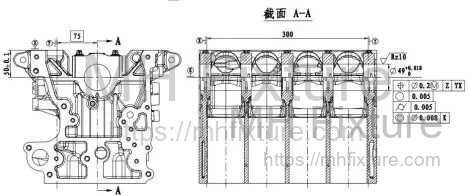
Crankshaft Bore (Main Bearing) Specifications:
- Diameter Tolerance: 0 to +0.018 mm.
- Roughness: 10 μm.
- Position: 0.2 mm.
- Roundness: 0.005 mm.
- Cylindricity: 0.005 mm.
- Coaxiality: 0.008 mm (specifically between bearing journals #2, #3, and #4).
2. Process Control: Top Deck Finish Milling
The machining of the top deck creates the primary sealing surface for the cylinder head gasket. Process stability here is paramount to prevent leakage and ensure compression.
2.1 Fixture Design and Datum Management
The clamping strategy must align with the datum reference frame defined in the engineering drawings.
- Datum Consistency: Since the bottom face and its two locator pin holes are machined in previous operations, they serve as the primary locating datum. Using the same datum for finish milling eliminates stack-up errors associated with datum transfer.
- Auxiliary Support: Given the large spatial volume and thin-walled nature of engine blocks, standard clamping can induce elastic deformation. The fixture design must incorporate self-locking auxiliary supports (work supports) to dampen vibration and prevent chatter without distorting the part.
- Clamping Force Distribution: Clamping forces must be distributed uniformly to prevent stress accumulation, which can lead to "spring-back" deformation after the part is released, compromising flatness.
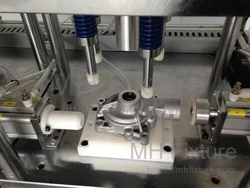
2.2 Process Monitoring and Tooling
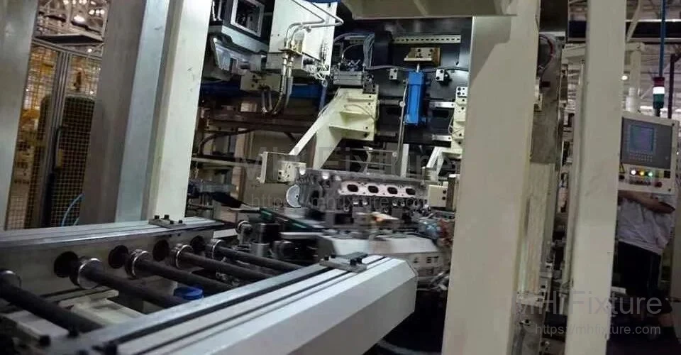
- Pneumatic Seating Check: The machining center is equipped with a 3-point pneumatic detection system. If the workpiece does not seat perfectly against the locators (indicating chip interference or misalignment), the machine triggers an alarm, preventing non-conforming processing.
- CBN Tooling Application: Cubic Boron Nitride (CBN) inserts are mandatory for high-volume finishing. Unlike carbide, which may degrade surface finish quality () after 100 cycles, CBN maintains consistency for 200+ cycles, ensuring productivity and stable roughness values.
- Path Optimization: CNC toolpaths are optimized to manage cutter engagement and exit forces, preventing edge breakout or flatness deviations at the block boundaries.
2.3 Environmental and Post-Process Control
- Deburring: An automated brushing cycle follows the face milling path to remove burrs immediately.
- Thermal Control: The workshop maintains a strict environment of 20±2°C and 40–60% humidity to negate thermal expansion effects on dimensional metrology.
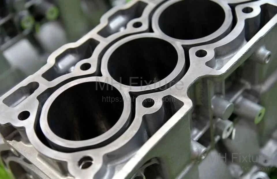
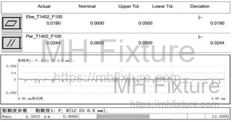
The resulting quality parameters for flatness and parallelism are verified in the report below.
3. Process Control: Cylinder Bore Machining
Cylinder bore quality determines piston ring sealing and oil consumption. The process involves a strict sequence of fine boring followed by multi-stage honing.
3.1 Pre-Honing Fine Boring
Before honing, the bore geometry must be established. The bore is fine-bored to a tolerance of ±0.01 mm, leaving a consistent stock allowance of 0.04–0.05 mm for the honing process.
- Thermal Management: Fine boring tools utilize internal through-tool coolant to evacuate chips and dissipate heat, preventing thermal distortion of the bore walls.
- Metrology: Post-boring, an in-line pneumatic gauge verifies the diameter. Only blocks within the allowable tolerance range are conveyed to the honing station.
3.2 Vertical Honing Process
The honing process uses an expansion mechanism where abrasive stones apply radial pressure to the bore wall.
- Tooling: The honing head typically carries 6–9 abrasive sticks (6 for roughing, 9 for finishing).
- Kinematics: The tool reciprocates at 25–35 m/min while rotating. The ratio of rotation to reciprocation speed determines the cross-hatch angle (typically 20°–30°), which is critical for oil retention.
- Pressure Control: Stone pressure is regulated between 0.3–0.5 MPa. This ensures optimal material removal rates without inducing excessive stress or glazing the stones.
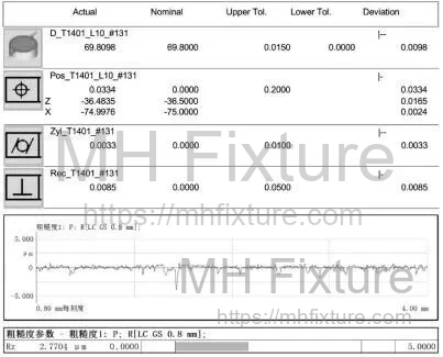
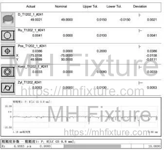
The final inspection report confirms diameter, cylindricity, and surface texture compliance.
4. Process Control: Crankshaft Bore (Line Boring)
The crankshaft main bearing bores require exceptional coaxiality to support the crankshaft rotating at speeds up to 6,000 RPM.
4.1 Deep Hole Line Boring
The crankshaft bore, often exceeding 300 mm in depth, presents a challenge for tool rigidity.
-
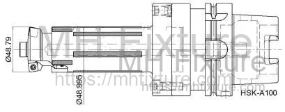
Tooling Structure: A specialized multi-step line boring bar is used. This tool features guide pads and distinct cutting zones (semi-finish and finish inserts) to maintain straightness.
-
Operation Sequence:
- Pilot: The tool opens the lead bore.
- Semi-Finish: Material is removed to a diameter of 48.79 mm.
- Finish: The final pass achieves 48.995 mm, leaving 0.04–0.05 mm for honing.
-
Multi-Axis Machining: The process typically bores journals #1 and #2, then rotates the table to machine #5, #4, and #3 to maximize access and stability.
4.2 Plateau Honing
Plateau honing creates a surface profile with flat peaks (load-bearing) and deep valleys (oil retention). Compared to conventional honing, this technique:
- Reduces engine break-in time by 30–50%.
- Increases engine life by 10–20%.
- Reduces oil consumption by 50–60%.
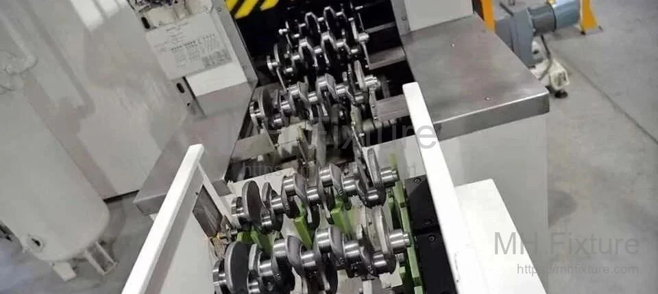
The honing mandrel processes all journals simultaneously (from #1 to #5) to guarantee coaxiality (0.008 mm) and cylindricity (0.005 mm).
Summary
The mass production of automotive cylinder blocks demands a rigorous integration of manufacturing technologies. By utilizing Automotive Fixture Solutions, high-performance CBN tooling, and precise environmental controls, manufacturers can ensure consistent adherence to micron-level tolerances, ultimately guaranteeing the performance and durability of the final engine assembly.