Hydraulic Fixture Design for Automated Machining of Automotive Flywheel Shells
Machining thin-walled automotive flywheel shells presents significant challenges regarding deformation and vibration control. This article details a hydraulic fixture design utilizing automatic centering and hydraulic auxiliary supports to ensure dimensional stability during CNC operations. The integrated solution enables robotic automation with a non-machining cycle time of just 16.6 seconds.
The automotive manufacturing sector has transitioned significantly from rigid transfer lines to flexible manufacturing systems (FMS). As vehicle models update rapidly to meet performance and aesthetic demands, production lines require high adaptability. Modern machining relies heavily on CNC machining centers integrated with industrial robots, where the flexibility of the system often hinges on the design of the dedicated workholding fixtures.
This article analyzes the engineering challenges associated with machining automotive flywheel shells and presents a robust hydraulic fixture solution designed for automation, high precision, and minimal cycle times.
1. Component Analysis and Engineering Challenges
The flywheel housing is a critical structural component located between the engine and the gearbox. It connects the crankcase to the oil pan, houses the flywheel assembly, and ensures the alignment of the transmission system.
Geometric and Material Characteristics
The flywheel shell is typically a cast iron or aluminum alloy component characterized by a basin-like structure.
- Dimensions: Approximately Ø500mm diameter and 200mm height.
- Structure: Complex geometry with non-uniform wall thickness. The walls vary significantly, ranging from thick structural sections (approx. 40mm) to thin-walled areas (4-5mm).
- Machining Requirements: The component features two large mating surfaces connecting the engine and clutch, requiring high flatness and surface finish to ensure proper sealing and mechanical stability.
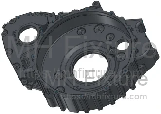 Figure 1: 3D Model of the Automotive Flywheel Shell
Machining Challenges
Due to the large surface area and thin-walled structure, the part is highly specific to:
- Clamping Deformation: Excessive radial force can distort the thin walls, leading to out-of-tolerance dimensions once released.
- Machining Vibration (Chatter): Insufficient rigidity in the central thin sections can cause vibration during face milling.
- Positioning Complexity: The irregular casting shape makes establishing a consistent datum difficult.
2. Clamping Strategy and Locating Principles
To guarantee machining quality, the fixture design focuses on the "Six-Point Location Principle" while addressing the rigidity issues inherent to the workpiece.This sophisticated interplay of forces is a core standard in our custom CNC hydraulic fixture solutions, ensuring zero-defect manufacturing for complex castings.
Locating Scheme
Given the irregular shape, an automatic centering mechanism is employed for radial positioning.
- Primary Datum: Three main support points (Z-axis) define the machining plane.
- Centering: An expanding mandrel or hydraulic centering device locates the central bore, establishing the geometric center.
- Angular Orientation: A Y-direction push mechanism restricts rotation.
Clamping and Support Logic
To counteract cutting forces without inducing deformation, the fixture utilizes a combination of main and auxiliary clamping:
- Main Clamping: Three primary hydraulic swing clamps apply force directly over the main support points.
- Auxiliary Support: To dampen vibration and prevent deformation in thin areas, four hydraulic work supports (auxiliary supports) are deployed. These supports engage the workpiece after it is positioned but before the auxiliary clamps are applied.
- Auxiliary Clamping: Three additional clamping points work in conjunction with the supports to maximize rigidity.
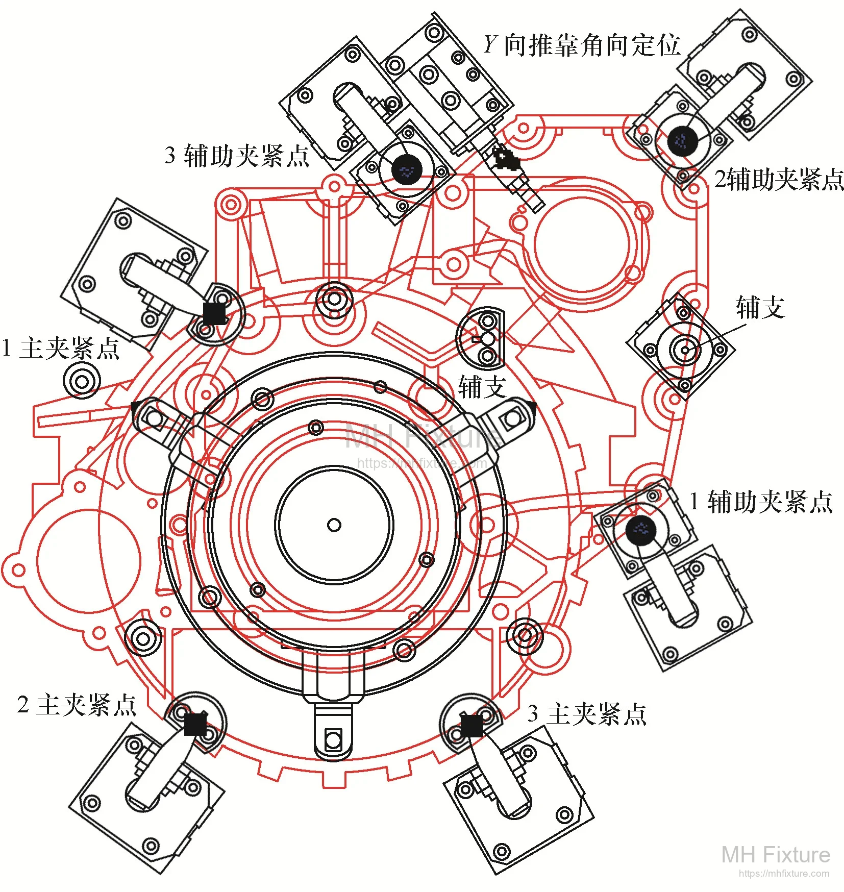 Figure 2: Positioning and Clamping Layout
3. Structural Design of the Fixture
The fixture is designed as a self-contained hydraulic unit compatible with CNC vertical machining centers.
Key Components
- Base (16): Precision-ground fixture body with standard alignment keys for rapid installation on the machine table.
- Centering Device (1): A hydraulic cylinder actuates the vertical movement to engage the workpiece center.
- Clamping Elements:
- Main Clamps (3, 4): Hydraulic cylinders driving swing clamp arms.
- Auxiliary Supports (5, 9, 12, 13): Hydraulic self-adjusting supports that lock in position upon contact.
- Auxiliary Clamps (6, 10): Secondary clamps to secure the perimeter.
- Seating Verification: An integrated air sensing system (pneumatic check) ensures the workpiece is flush against the locators before the machine cycle begins.
 Figure 3: Detailed Fixture Assembly and Component Identification
(1. Centering Device, 2. Limit Column, 3/10. Clamping Cylinders, 4/6. Clamps, 5/9/12/13. Auxiliary Support Cylinders, 7. Angular Cylinder, 15. Tool Setting Device)
Figure 3: Detailed Fixture Assembly and Component Identification
(1. Centering Device, 2. Limit Column, 3/10. Clamping Cylinders, 4/6. Clamps, 5/9/12/13. Auxiliary Support Cylinders, 7. Angular Cylinder, 15. Tool Setting Device)
4. Automation Integration and Cycle Sequence
The fixture is designed for full integration with robotic loading/unloading systems. The internal hydraulic and pneumatic circuits connect to the machine tool via a rotary joint or quick-disconnect interface.
Operational Sequence
The total non-machining cycle time (loading, clamping, unloading) is optimized to 16.6 seconds. The sequence is as follows:
- Robot Loading: The manipulator places the raw casting into the fixture.
- Initial Positioning: The centering device expands/lifts to locate the bore.
- Orientation: The angular cylinder pushes the part against the rotation stop.
- Main Clamping: Primary clamps engage.
- Seating Check: Pneumatic sensors verify the part is correctly seated (Air Check). If successful, the cycle proceeds.
- Support Engagement: Auxiliary supports extend and lock to provide rigidity without lifting the part.
- Final Clamping: Auxiliary clamps engage.
- Machining: The CNC cycle executes.
- Unloading: Sequence reverses for robotic removal.
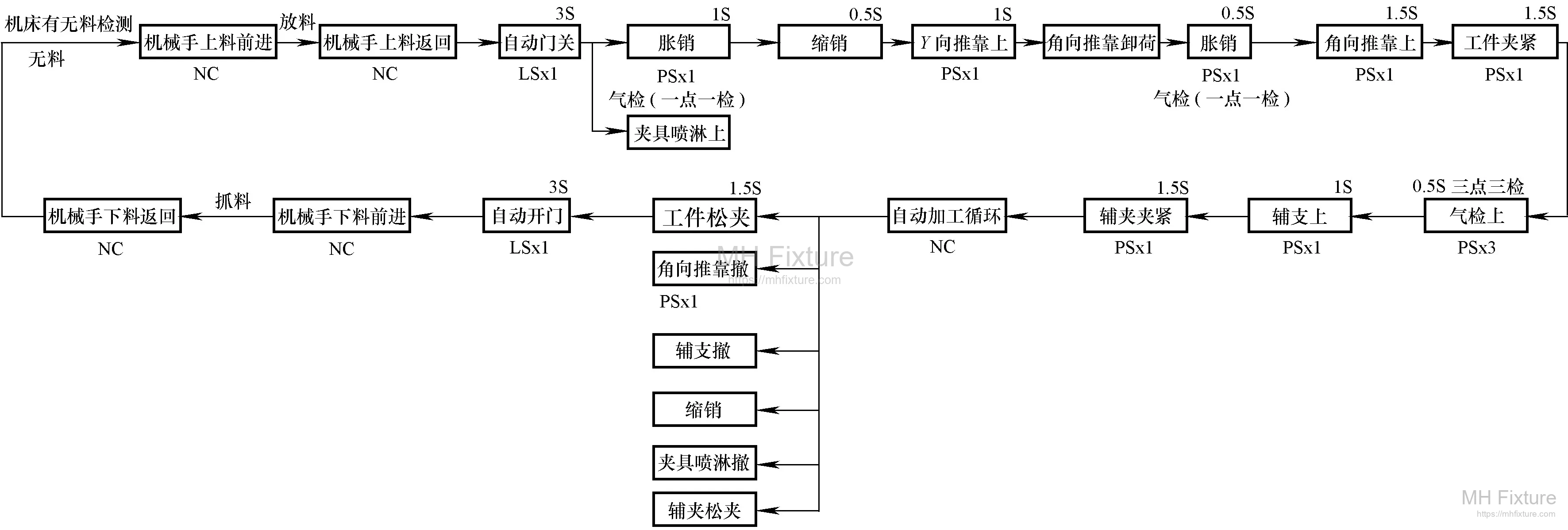 Figure 4: Automation Logic and Signal Flow Chart
5. Engineering Conclusion
This hydraulic fixture design successfully addresses the deformation and efficiency challenges associated with flywheel shell manufacturing. By combining automatic centering with a robust auxiliary support system, the design achieves:
- Process Stability: Elimination of clamping-induced distortion, maintaining tight flatness tolerances.
- High Efficiency: A reduced non-cutting cycle time of 16.6 seconds through seamless robotic integration.
- Quality Assurance: Integrated pneumatic seating detection prevents machining errors caused by improper loading.
Validation runs have demonstrated a near 100% first-pass yield acceptance rate, proving the design's effectiveness for high-volume, intelligent automotive manufacturing environments.
If you are looking to integrate similar high-efficiency workholding into your FMS, MH Fixture offers expert automotive fixture design and manufacturing to meet your specific cycle time goals.