Hydraulic Rotary Fixture Design: Optimizing Gearbox Housing Machining on VMCs
Machining complex gearbox housings on vertical machining centers (VMC) often presents challenges with coaxality and multi-face access. This technical article details a custom hydraulic rotary fixture design that enables 180° indexing and single-setup machining for HT200 cast iron housings. The solution eliminates the need for expensive horizontal boring machines while ensuring dimensional stability.
Gearbox housings are characterized by complex hole systems, strict coaxality requirements, and large dimensional spans. Traditional process planning often dictates the use of Horizontal Machining Centers (HMC) or horizontal boring machines to access multiple sides. However, these machines incur high operational costs.
For many manufacturers, utilizing a standard Vertical Machining Center (VMC) is a more cost-effective alternative, provided the workholding solution can overcome the machine's axis limitations. This article analyzes a custom fixture design solution developed for an automotive manufacturer, addressing the challenge of machining a gearbox housing with high-precision requirements on a 3-axis VMC.
1. Process Analysis and Engineering Requirements
The project originated from a specific request to move a new gearbox product from HMC to VMC production lines without compromising quality.
Part Specifications
The workpiece is a gearbox housing with the following parameters:
- Dimensions: Approx. 425mm × 210mm × 105mm
- Material: HT200 (Grey Cast Iron)
- Hardness: 190 HBS
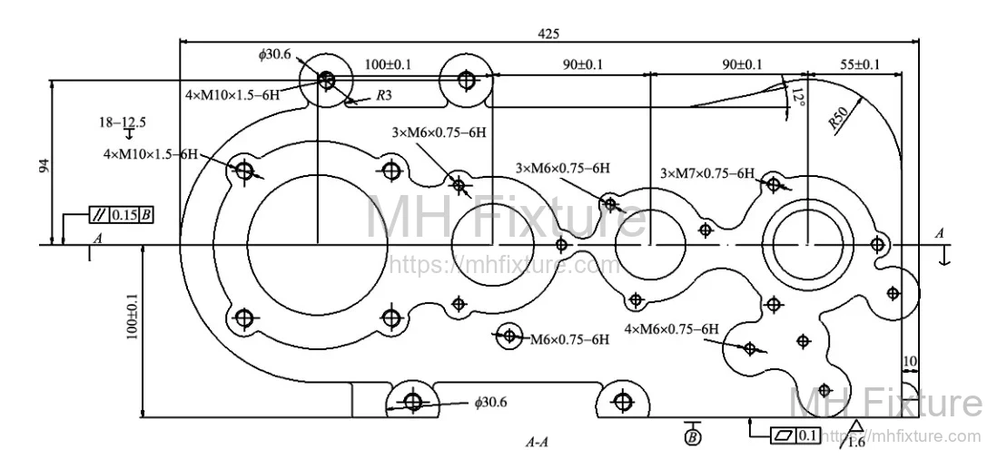
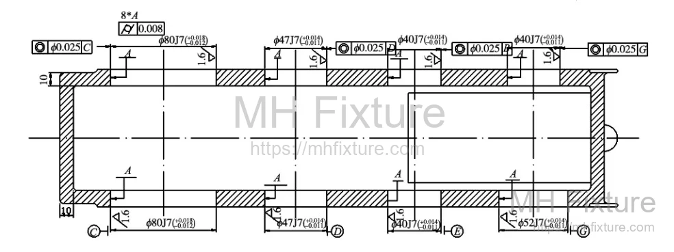 Figure 1: Gearbox Housing Structure
Critical Machining Features
- Bearing Bores: Four sets of coaxial holes on opposing sides (2× Ø80J7, 2× Ø47J7, Ø52J7, 3× Ø40J7).
- Auxiliary Holes: Multiple smooth bores and threaded holes distributed around the ports (Ø10, Ø14, M10-6H, M6-6H).
- Surface Finish: Ra1.6μm for bearing bores and bottom surfaces; Ra6.3μm for side bosses and threaded holes.
The Engineering Challenge
The primary challenge lies in the coaxality of the bearing bores across a large span. In a standard VMC setup, the Z-axis limitation prevents simultaneous access to opposing faces. Machining one side, manually flipping the part, and machining the other introduces significant positioning errors, making it difficult to maintain coaxality.
Process Strategy: To guarantee precision, the process requires a "unified benchmark" approach. The part must be located using three planes, clamped once, and rotated 180° around the 100mm axis to machine both sides in a single setup. Prior to this operation, the three datum surfaces are finish-milled.
2. Technical Solutions for Non-Standard Requirements
The transition from HMC to VMC required addressing three specific technical hurdles.
Challenge 1: Machine Selection
Requirement: Abandon the traditional horizontal boring/milling process in favor of a vertical machining center. Solution: Design a specialized fixture tailored for the VMC workspace that compensates for the lack of a horizontal spindle.
Challenge 2: Cycle Time and Ergonomics
Requirement: Eliminate manual re-clamping between faces to reduce downtime and operator fatigue. Solution: Implement an automated rotation mechanism within the fixture. Since standard VMCs lack a rotary table (4th axis), the fixture itself must provide the rotation capability to machine upper and lower faces in one clamping cycle.
Challenge 3: Precision and Actuation
Requirement: Achieve precise 180° rotation and maintain positioning accuracy during heavy cutting loads. Solution: Integrate a hydraulic system. A hydraulic rotary actuator handles the motion, while the fixture's structural design ensures rigid locking and precise positioning repeatability.
3. Detailed Fixture Design
The resulting design is a hydraulic rotary fixture that transforms a 3-axis machine into a pseudo-4-axis production cell.
3.1 Locating and Clamping Strategy
- Location: The part is located using the 3-2-1 principle. The fixture body utilizes three support plates and one support pin to establish a definitive spatial reference.
- Clamping: A dual-cylinder hydraulic system is employed. This ensures consistent clamping force, eliminates operator variation, and supports high-volume production cycles.
3.2 Rotation Mechanism
Because the VMC spindle cannot rotate relative to the workpiece horizon, the fixture rotates the workpiece. The axis of rotation is aligned with the workpiece's 100mm dimension axis. A hydraulic rotary actuator (swing cylinder type) drives the rotation, providing smooth, rapid indexing with high angular precision.
3.3 Structural Configuration
The mechanical assembly consists of a base, a trunnion-style fixture body, and hydraulic components.
- Base: Rigidly mounted to the machine table via T-slots.
- Fixture Body (Trunnion): Holds the workpiece and rotates between two vertical supports.
- Locating Elements: As shown in Figure 2, bottom positioning blocks (4, 6) and side blocks (14, 7) constrain the six degrees of freedom.
 Figure 2: Fixture Structure Assembly
Key Components: 1. Base, 2. Fixture Body, 3/8. Rotary Connection Plate, 10. Hydraulic Rotary Actuator, 12/13. Swing Clamp Cylinders.
3.4 Clamping Actuation
Two swing clamp cylinders (corner cylinders) are mounted directly on the fixture body.
- Action: These cylinders rotate into position and pull down to clamp.
- Advantage: During loading/unloading, the clamp arms swing away, providing unobstructed clearance for the operator or robotic loader. The rotation angle is set to avoid interference with the workpiece housing.
4. Hydraulic Control System Design
The fixture relies on a sequence-controlled hydraulic circuit to manage clamping and rotation logic.
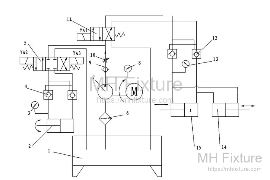 Figure 3: Hydraulic Control System Schematic
Operational Sequence
- Clamping: The hydraulic pump activates. Solenoid valve (11) energizes, directing pressure to the clamping cylinders (14, 15). The workpiece is secured.
- Machining Side A: The VMC performs operations on the first face.
- Rotation (Indexing): Upon completion of Side A, solenoid valve (5-YV2) energizes. The rotary actuator (2) rotates the fixture body 180° clockwise. A limit switch confirms the position, YV2 de-energizes, and the system maintains pressure to lock the position.
- Machining Side B: The VMC machines the opposing face.
- Reset: Solenoid valve (5-YV3) energizes, rotating the fixture counter-clockwise back to the origin.
- Unclamping: Valve (11) de-energizes/reverses, releasing the clamp pressure for part removal.
5. Engineering Conclusion
This hydraulic fixture design successfully bridges the gap between VMC affordability and HMC capability. By integrating a hydraulic rotation system, the manufacturer achieved:
- Higher Precision: Single-setup machining guarantees the coaxality of bearing bores.
- Increased Efficiency: Elimination of manual turning and secondary setups reduces auxiliary time.
- Cost Reduction: Maximized utility of existing VMC assets without investing in expensive 4-axis tables or HMCs.
Related Case Studies
Similar non-standard hydraulic solutions have been deployed across the automotive sector:
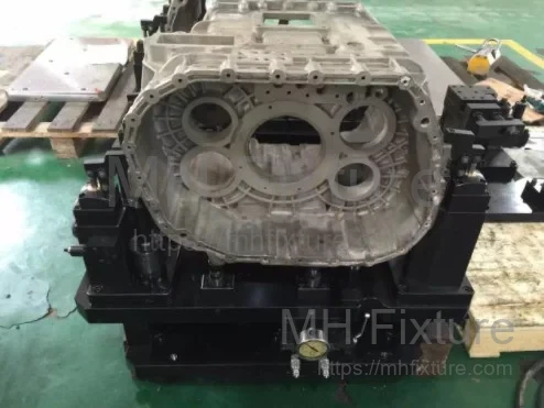
- 8AT Gearbox Manufacturer: Custom hydraulic fixture suite.
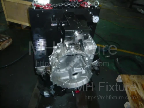
- CNHTC (Sinotruk): Intermediate housing hydraulic fixtures.
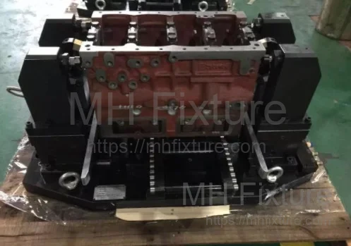
- Diesel Engine Plant: 4-cylinder block vertical machining fixtures.
For detailed specifications and more engineering examples, please visit our Hydraulic Fixtures Category.