Design of a Multi-Station Quick-Change Fixture for High-Volume Castings
High-volume machining of cast parts often suffers from efficiency bottlenecks due to single-station setups. This case study details the design of a 20-station quick-change fixture utilizing spring-loaded pressure mechanisms to compensate for casting tolerances. The solution significantly reduces non-cutting time and ensures consistent positioning accuracy.
1. Introduction
In the mass production of relatively simple components, machining efficiency is frequently compromised by the setup process. If a production line relies on single-part clamping, the frequency of loading, unloading, and machine start-stop cycles creates significant non-cutting time. This not only bottlenecks throughput but also increases operator fatigue.
To address this, manufacturing engineers must transition from single-station setups to dedicated high-efficiency fixture solutions. This article analyzes the design of a multi-station quick-change fixture capable of clamping 20 components simultaneously. This approach drastically reduces the frequency of clamping operations, facilitates rapid changeovers, and optimizes the machining cycle for cast components with inherent dimensional variations.
2. Component Analysis and Process Challenges
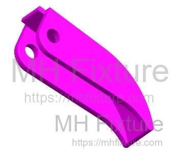
The subject component (see Figure 1) is a casting blank. Due to the casting process, each part exhibits slight dimensional variations in its external profile. The initial machining process for the small holes on the part faced several critical issues:
- Low Efficiency: As shown in Figure 2, the original setup processed only one workpiece per cycle. The time spent loading and unloading consumed a disproportionate amount of the total lead time.
- High Labor Intensity: The repetitive nature of single-part clamping caused significant operator fatigue.
- Cost Implications: The extended processing cycle increased machine occupancy costs and delayed production schedules.
To resolve these bottlenecks, a dedicated multi-station quick-change fixture (see Figure 3) was developed.
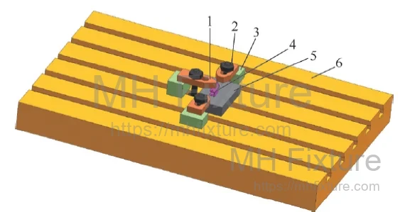 1—Strap Clamp; 2—Nut; 3—Spacer Block;
4—Workpiece; 5—Fixture Base; 6—Machine Table
1—Strap Clamp; 2—Nut; 3—Spacer Block;
4—Workpiece; 5—Fixture Base; 6—Machine Table
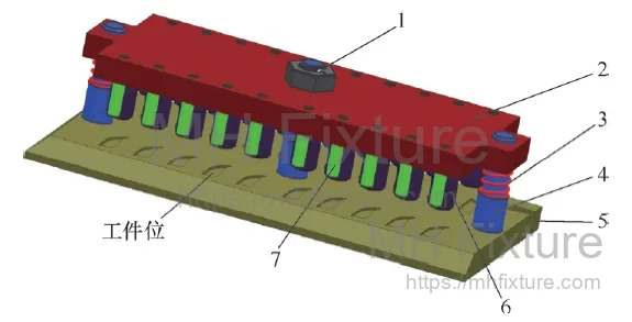 1—Clamping Screw & Nut; 2—Top Plate; 3—Return Spring; 4—Guide Pillar;
5—Base Plate; 6—Pressure Mechanism; 7—Drill Bushing
1—Clamping Screw & Nut; 2—Top Plate; 3—Return Spring; 4—Guide Pillar;
5—Base Plate; 6—Pressure Mechanism; 7—Drill Bushing
3. Fixture Design and Engineering Logic
The core objective was to design a fixture capable of holding 20 workpieces for simultaneous processing. The clamping mechanism allows all 20 parts to be secured or released by tightening or loosening a single central nut.
To maximize spindle uptime, two identical fixtures were manufactured to facilitate an offline loading strategy (external setup). Furthermore, the interface between the fixture and the machine table utilizes a quick-positioning mechanism, requiring only one bolt for final securing. Integrated drill bushings ensure tool guidance and prevent deflection.
3.1 Design Details
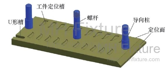
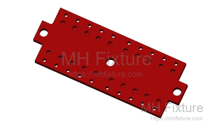
1. Base Plate Design The base plate (see Figure 4) features 20 positioning pockets. To accommodate the casting tolerances, the pocket profile matches the workpiece's maximum contour but is oversized by 0.2mm, with a depth of 1mm. This resolves positioning for multiple parts simultaneously. The base includes guide pillars on the left and right, with a central threaded rod for clamping actuation.
2. Top Plate Design The top plate (see Figure 5) acts as the main clamping carrier. It contains:
- 20 blind holes for installing the spring-loaded pressure mechanisms.
- 20 through-holes for installing drill bushings.
- Two guide holes on the sides (precision fit with the guide pillars) to ensure vertical alignment during clamping.
- A central clearance hole for the main clamping screw.
3. Elastic Pressure Mechanism (Compensating for Tolerance) A critical engineering challenge was the dimensional variation of the cast blanks (mm difference). A rigid clamping plate would fail to secure smaller parts if larger parts bottomed out first.
To solve this, an elastic pressure mechanism (see Figure 6) was designed. It consists of a strut, guide sleeve, spring, and pin. During the clamping stroke, the spring compresses individually for each station, allowing the mechanism to adapt to height variations and ensuring every workpiece is securely held with sufficient down-force.
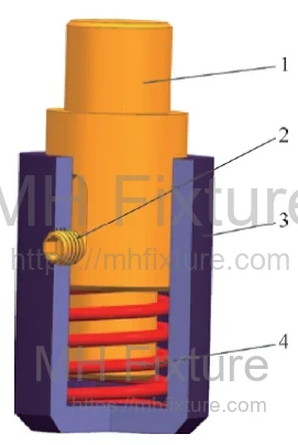 1—Plunger Post; 2—Retaining Pin; 3—Guide Sleeve; 4—Compression Spring
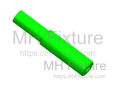
4. Drill Bushing Selection Hardened drill bushings (see Figure 7) are utilized to guide the drill bit. Heat-treated to 50 HRC, these bushings prevent tool deflection (wandering), ensuring the hole position accuracy meets the engineering requirements.
5. Return Springs To facilitate easy loading, return springs are installed on the guide pillars. These lift the top plate automatically when the central nut is loosened, creating clearance for part removal.
6. Quick-Change Positioning System To minimize downtime during fixture swaps, the base plate features angled positioning surfaces on two sides and a U-slot on the opposing corner (see Figure 4).
- Machine Side: Positioning blocks are fixed to the machine table.
- Operation: The fixture base is slid against the positioning blocks. A single T-nut and bolt in the U-slot secures the fixture. This eliminates the need for dial indicator alignment during every changeover.
3.2 Operational Workflow
- Fixture Assembly: As shown in Figure 3, the 20 pressure mechanisms and drill bushings are installed into the top plate. The top plate is then mounted onto the base plate via the guide pillars and central screw, supported by the return springs.
- Machine Setup: Two positioning blocks are installed along the X-axis (long side) and one along the Y-axis (short side) of the machine table. These are aligned using a dial indicator to ensure parallelism with the machine axes.
- Fixture Installation: The assembled fixture is placed on the table, pushed against the positioning blocks, and clamped via the U-slot.
- Part Loading: 20 workpieces are placed into the positioning pockets. The central nut is tightened, compressing the top plate. The individual spring-loaded mechanisms engage each part securely (see Figure 8).

- Machining: The CNC cycle executes the drilling operation (see Figure 9).
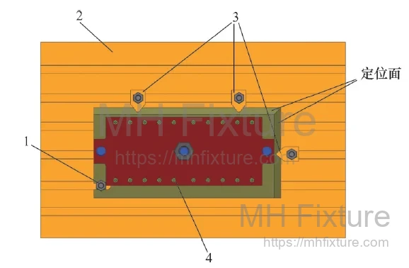 1—Clamping Nut; 2—Machine Table; 3—Positioning Block; 4—Workpiece
- Cycle Optimization: By using two identical fixtures, the operator loads the second fixture while the first is being machined. Once the cycle ends, the fixtures are swapped immediately. This "internal time vs. external time" optimization ensures the machine runs continuously.
4. Conclusion
This multi-station quick-change fixture has been validated in a production environment to deliver substantial gains in manufacturing efficiency. By integrating batch clamping, tolerance compensation via spring mechanisms, and rapid fixture changeover protocols, the design addresses the core challenges of machining cast components.
Key benefits include:
- Reduced Auxiliary Time: Minimizes setup and tool change overhead.
- Improved Ergonomics: Significantly lowers physical labor for operators.
- Quality Stability: Drill bushings and consistent clamping pressure ensure repeatability.
For manufacturers looking to optimize their production lines, adopting such modular clamping systems is a proven strategy to reduce costs and increase capacity.Looking to further improve your production efficiency or develop customized tooling solutions for specific cast parts? Our senior engineering team is ready to provide professional technical consultation and solution evaluations.
Please Contact Us to start your production optimization journey with our technical experts.