High-Rigidity Fixture Design for Shifting Fork Milling Applications
Milling low-rigidity parts like shifting forks often leads to severe chatter and dimensional instability. This engineering case study details a high-rigidity fixture design utilizing mandrel location and adjustable auxiliary supports to eliminate vibration. The solution ensures process reliability and prevents tool breakage during heavy cutting loads.
Introduction
Milling specialized components with low structural rigidity—such as gear shifting forks—presents a distinct set of manufacturing challenges. The lack of inherent stiffness often results in severe vibration (chatter) during material removal, leading to premature tool failure, loosening of clamping elements, and compromised dimensional accuracy.
For manufacturing engineers, addressing these dynamic instability issues requires moving beyond standard vise setups. Implementing robust, custom-engineered tooling is essential. Whether utilizing complex hydraulic fixture systems or precision mechanical jigs, the primary objective remains the same: maximizing rigidity to ensure process capability (). This article analyzes a specific mechanical fixture design engineered to eliminate vibration during the milling of a steel shifting fork.
Engineering Challenge and Process Analysis
The workpiece in question is a shifting fork that requires precision milling on two parallel faces to a dimension of 7mm. Prior to this operation, a mm bore and a 13.5mm slot have already been machined.

Geometric Constraints and Degrees of Freedom
To ensure the machined faces meet the strict perpendicularity and position tolerances required for the transmission assembly, the fixture design adheres to the principle of datum coincidence:
- Primary Datum: The mm bore is used to restrict four degrees of freedom (DOF) via a long mandrel fit.
- Secondary Datum: The side face of the 13.5mm slot is used to restrict rotation around the bore axis.
Since the operation only involves milling the side faces, restricting these specific degrees of freedom constitutes a "partial location" strategy, which is sufficient and efficient for this specific process.
The Problem with Previous Methods
Initial attempts utilized a cantilevered mandrel approach where the clamping point was distant from the cutting zone. This setup lacked sufficient stiffness, acting as a cantilever beam under cutting forces. The resulting deflection caused:
- Excessive vibration and noise.
- High incidence of carbide insert chipping.
- Inability to hold the mm tolerance.
Fixture Design and Structural Logic
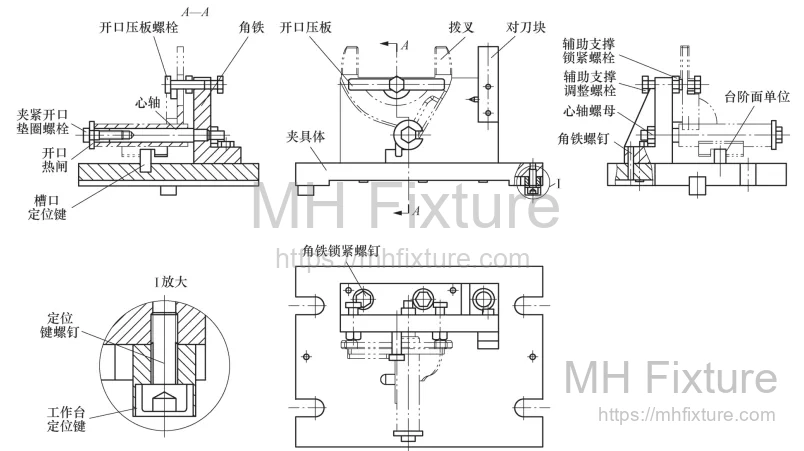
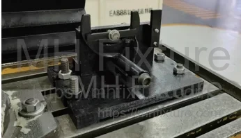
To resolve the rigidity issues, a dedicated high-rigidity milling fixture was developed. The assembly is detailed in Figure 2, with the physical implementation shown in Figure 3.
Key Structural Components
-
Fixture Body & Base: An angle plate structure provides the perpendicular backbone. It is secured to the machine table using standard T-nuts and aligned via locating keys.
-
Locating Mechanism:
- A mandrel is press-fitted into the angle plate to locate the mm bore.
- A slot locating key engages with the 13.5mm slot on the workpiece to prevent rotation.
-
Dual Clamping System:
- Axial Clamping: A threaded stud extends from the mandrel. An open washer (U-washer) and nut apply axial force, seating the workpiece against the locator face.
- Radial/Vertical Clamping: An open clamp plate presses on the fork ends, secured by bolts into the angle plate. This applies pressure directly near the cutting zone.
-
Auxiliary Support:
- To counteract cutting forces and dampen vibration, adjustable auxiliary support bolts are positioned behind the fork's weak sections. These are locked in place with jam nuts once touching the part.
Operational Workflow
The loading sequence is critical to preventing clamping-induced distortion while ensuring rigidity:
- Load: Slide the workpiece bore onto the mandrel, ensuring the 13.5mm slot seats against the locating key.
- Primary Clamp: Insert the open washer onto the mandrel stud and tighten the nut. This establishes the primary location.
- Support: Adjust the auxiliary support bolts until they lightly contact the back of the workpiece face, then lock the jam nuts. Note: Over-tightening here will distort the part.
- Secondary Clamp: Slide the open clamp plate over the vertical studs and tighten. This provides the necessary rigidity for milling.
- Machining: Execute the milling program.
- Unload: Reverse the sequence for part removal.
Technical Features and Engineering Advantages
1. Datum Alignment Strategy
By utilizing the pre-machined slot as a rotational reference (Figure 4), the fixture ensures the milled faces are perfectly aligned with the component's functional axis.

2. Multi-Point Clamping Distribution
The fixture separates location retention from cutting force resistance.
- Force A (Axial): Ensures the part remains seated against the datum.
- Force B (Vertical): The open clamp plate acts directly against the cutting forces, preventing the "chatter" associated with the previous cantilever design.
3. Tunable Rigidity via Auxiliary Supports
The inclusion of adjustable supports is the critical factor in stabilizing this thin-walled part. They effectively reduce the unsupported length of the workpiece, increasing the natural frequency of the setup and moving it outside the range of excitation frequencies generated by the cutter.
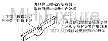
4. Rapid Changeover Design
Both the axial washer and the vertical clamp plate utilize open (U-slot) designs. This allows operators to loosen bolts without fully removing them, significantly reducing load/unload cycle times (Figure 6).

Conclusion
In precision manufacturing, the safety and efficiency of milling operations are directly dictated by fixture rigidity. For complex geometries like shifting forks, standard clamping is often insufficient. By integrating auxiliary supports and a dual-clamping mechanism, this fixture design successfully eliminated vibration, stabilized tolerances, and extended tool life.
For manufacturers facing similar challenges with unstable parts, investing in dedicated custom fixture solutions is the most effective path to reducing scrap rates and optimizing production throughput.