Fixture Design Optimization for Automotive Steering Gear Housings: A Case Study in Efficiency and Precision
Machining complex aluminum steering gear housings presents significant clamping challenges regarding deformation and efficiency. This case study details the transition from 5-axis machining to a high-volume horizontal machining center (HMC) process using custom multi-station fixtures. The optimized design ensures angular precision of 16°±3' while reducing cycle time by approximately 50%.
Editor's Note This article analyzes the engineering characteristics of automotive steering gear housings and presents a specific fixture design solution for aluminum alloy casting machining. It details the transition from prototype machining to mass production, summarizing key design principles for minimizing deformation and maximizing throughput.
1. Introduction
The steering gear housing is a critical structural component in automotive steering systems, ensuring precise linkage between the steering wheel and the wheels. It serves as the mounting base for bearings, worm gears, and transmission shafts. Its primary engineering functions include:
- Ensuring accurate bearing alignment.
- Maintaining precise center distance between the worm and gear for stable transmission output.
- Providing rigid mounting interfaces to the vehicle chassis.
High geometric precision in the housing is essential to prevent internal component wear, extend service life, and ensure the rigidity and response speed of the steering system.
While modern manufacturing relies heavily on 5-axis CNC machine tools to simplify tooling requirements, this is not always the most cost-effective solution for mass production. Complex, dedicated fixtures designed for standard Horizontal Machining Centers (HMCs) often outperform general-purpose 5-axis machining in terms of cycle time and operational costs. This case study demonstrates how a dedicated fixture design, combined with existing production resources, offers a superior process solution for steering gear housings.
2. Component Analysis and Process Planning
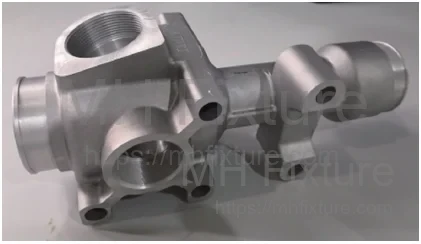
The component in focus is an aluminum alloy steering gear housing (Figure 1). It is a die-cast part with an irregular shape but high consistency in the blank stage. The machining requirements involve four faces, one of which includes features requiring an angular approach.

Key Technical Requirements:
- Machining Zones: Four distinct directional faces (indicated by frames in Figure 2) and bearing bores.
- Dimensional Tolerance: 0 to 0.02 mm for planes and bores.
- Angular Precision: The angled face requires 16° ±3'.
- Positional Tolerance: The distance between the feature bore axis on the angled face and the horizontal axis is 0 to 0.05 mm.
Process Strategy: Although the tolerance requirements are not extremely tight, the challenge lies in the multi-face machining of an irregular workpiece.
- 3-Axis Strategy: Would require 4 separate setups/fixtures, inducing cumulative errors and excessive handling time.
- 5-Axis Strategy: Allows for single-setup machining but suffers from higher machine hourly rates and lower material removal rates.
- Selected Strategy (HMC): Utilizing an HMC with a pallet changer allows for a two-stage process (Op 10 and Op 20). This enables continuous production—loading parts while the machine is running—significantly boosting efficiency.
3. Fixture Design and Engineering
Based on the process analysis, the workflow is divided into two operations:
- Op 10 (Fixture 1): Machining of faces 1, 3, and 4 (orthogonal faces) on Pallet A.
- Op 20 (Fixture 2): Machining of the angled face (face 2) on Pallet B.
The design was executed using CimatronE, ensuring seamless CAD/CAM integration.
3.1 Fixture 1 Design: Multi-Station Vertical Column
Fixture 1 is designed to machine three orthogonal faces using the HMC's B-axis rotation. To maximize spindle utilization, the fixture is designed as a vertical column (tombstone) holding three workpieces simultaneously.This configuration is a hallmark of custom HMC fixture solutions, which are engineered to balance extreme rigidity with high-density part loading.
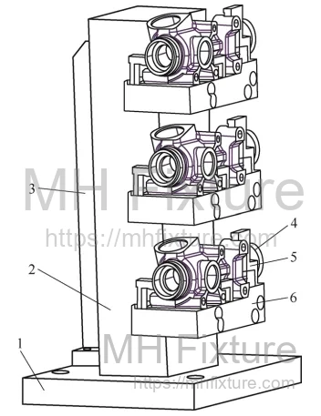
Design Features:
- Modular Assembly: Components are located via dowel pins and secured with high-strength bolts for ease of maintenance.
- Structural Rigidity: The column (100mm x 80mm x 420mm) is reinforced with ribs and secured to the base plate using mm pins and M12 bolts to withstand cutting forces.
- Six-Point Location Principle (3-2-1): Since the workpiece is a casting with no pre-machined datums, the "3-2-1" principle is applied using targeted contact points (Figure 4):
- Primary Datum (3 points): Three raised bosses on the support plate define the seating plane, restricting 3 degrees of freedom (DOF).
- Secondary Datum (2 points): Two stop blocks on the column restrict rotation and fore-aft movement.
- Tertiary Datum (1 point): A side stop restricts lateral movement.

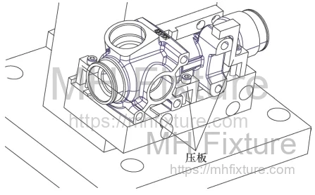
Clamping Strategy: To prevent deformation in the thin-walled aluminum casting, clamping forces are applied directly opposite the support points. Three clamp assemblies are positioned such that the pressure point aligns perfectly with the support bosses (Figure 5), neutralizing bending moments.
3.2 Fixture 2 Design: Angular Machining
Fixture 2 addresses the angled face (Frame 2 in Figure 2), requiring precision of 16° ±3' and bore positional tolerance of 0.05 mm.
Locating Method: The part is located using the "One Plane, Two Pins" method, utilizing surfaces machined in Op 10.
- Planar Location: The face machined in Op 10 rests on the fixture base, restricting 3 DOF (Z translation, rotations about X/Y).
- Pin Location: Two auxiliary datum holes (pre-machined in Op 10) engage with one round pin and one diamond (rhombic) pin. This restricts X/Y translation and rotation about Z.
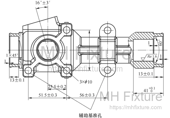
Angular Accuracy Control: Instead of interpolating the angle with the machine axes, the fixture is machined with the 16° angle built-in relative to the machine's X-axis. This allows for simple linear interpolation during machining.
Tolerance Verification: To ensure the angular tolerance of ±3' is met:
- The distance between locating pins is mm.
- The clearance between the pins ( mm) and the datum holes creates a controlled fit.
- Calculation: A deviation of 3' over a length of 107.5 mm corresponds to a vertical displacement of approximately mm.
- By maintaining pin/hole clearances within 0.03 mm and strictly controlling fixture geometry, the angular error is kept well within the allowable ±0.094 mm range.

4. Process Comparison and ROI Analysis
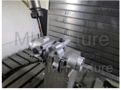
4.1 Scenario A: 5-Axis Machining (Prototyping)
As shown in Figure 8, the part can be machined in a single setup.
- Pros: Simple fixture, high theoretical accuracy, reduced operator skill requirement.
- Cons: Low throughput, high machine cost per hour. Cycle time: ~12 minutes/part. Machine stops for every load/unload.
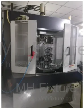
4.2 Scenario B: HMC with Dedicated Fixtures (Mass Production)
As shown in Figure 9, the customized fixture allows for batch processing.
- Pros: High efficiency, lower unit cost, consistent quality.
- Cons: Higher initial tooling design and manufacturing cost.
4.3 Efficiency Conclusion
- HMC: Processes 3 parts in 20 minutes (~6.7 min/part). The pallet changer allows loading/unloading during the machining cycle (masked time).
- 5-Axis: Processes 1 part in 12 minutes with zero masking of load time.
- Result: The HMC solution reduces cycle time by nearly 50% and utilizes a lower-cost machine platform, making it the superior choice for volume production.
5. Engineering Summary
- Performance Verification: The implemented fixture design proved to be rigid, efficient, and capable of consistently meeting the 16° ±3' angular requirement and 0.05 mm positional tolerances in a production environment.
- Design Guidelines for Aluminum Castings:
- 3-Point Support: Always prioritize a 3-point primary datum for raw castings to prevent rocking and instability.
- Clamping Alignment: Clamping forces must align directly with support points. Misalignment causes elastic deformation during machining, which releases as spring-back error once clamps are removed.
- Minimal Contact Area: Support points should have minimal surface area to ensure positive contact and avoid interference from casting irregularities.
For manufacturers seeking to achieve similar cycle time reductions and precision stability, MH Fixture offers expert custom automotive fixture design tailored to complex geometry and high-volume requirements.