Precision Clamping Strategy for Thin-Walled Aluminum Plate Milling
Thin-walled aluminum parts are prone to deformation during machining due to low rigidity and clamping stress. This case study details a precision axial clamping method using countersunk screws and low-depth-of-cut strategies to eliminate distortion. The process achieves thickness tolerances within 0.015mm and parallelism of 0.02mm for complex optical components.
Introduction
In precision optical and aerospace manufacturing, the design of thin-walled structural components focuses on minimizing mass while maintaining structural integrity. However, machining these components presents significant engineering challenges.
This article analyzes the process engineering for a high-precision, thin-walled lens barrel spacer, specifically addressing the challenges of clamping deformation and dimensional stability during the milling process.
Case Study Specifications:
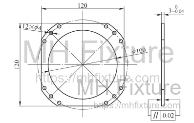
- Component: Lens Barrel Focusing Spacer (Figure 1)
- Material: Aluminum Alloy 2A12-T4 (Al-Cu-Mg)
- Dimensions: 3mm Finished Thickness
- Stock Allowance: 0.5mm
- Geometric Features: 0.3mm Hole Chamfers, curvilinear side walls
- Surface Quality:
Due to the low rigidity of the circular arc structure and the ductile nature of the material, standard clamping methods frequently result in geometric deviations that exceed tolerance limits.
Process Analysis and Challenges
Material and Geometry Constraints
The spacer has a wall thickness of only 3mm. While grinding is typically preferred for high-precision flatness, it is unsuitable for this application due to two primary factors:
- Material Properties: 2A12 aluminum is a non-ferrous, ductile alloy. Grinding wheels are prone to "loading" (clogging with chips), which nullifies the wheel's self-sharpening action and degrades surface finish.
- Workholding Limitations: Aluminum is non-magnetic, ruling out magnetic chucks. Furthermore, the thin profile cannot withstand the vacuum pressure or mechanical down-force of standard surface grinders without deflecting.
Limitations of Conventional Milling Clamping
Milling is the required process, yet standard fixtures fail to ensure stability:
- Vise Clamping: Applying radial pressure causes the thin-walled ring to buckle or deform elastically, resulting in "spring-back" errors after release.
- Toe Clamps/Step Blocks: While providing axial pressure, these clamps obstruct the tool path for face milling. This necessitates a segmented cutting process (moving clamps mid-process), which inevitably creates mismatch lines and compromises parallelism.
Solution: Countersunk Axial Clamping Method
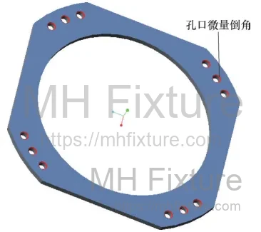
1. Engineering Principle
To eliminate radial distortion and tool path obstruction, the process utilizes Axial Clamping via Countersunk Screws. The design leverages the part's existing geometry—specifically the requirement for 0.3mm 45° chamfers on the four through-holes.
By utilizing flat-head (countersunk) screws, the clamping force is applied axially through the chamfered surface. Crucially, the screw head is seated below the machining allowance, allowing the face mill to pass uninterrupted over the entire surface.
2. Fixture Design
The setup involves a dedicated fixture plate (Figure 3) that provides:
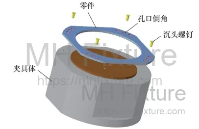
- Planar Reference: A precision-ground surface to mate with the component's bottom face.
- Radial Location: A central core or pin system to locate the part center.
- Axial Fixation: Four tapped holes corresponding to the component's pattern.
Expert Solution: Struggling with complex workholding? Explore our Custom Fixture Design Services to optimize your machining stability.
The screw head engages with the pre-machined chamfer. As the screw is torqued, the tapered head applies downward force, securing the part against the datum surface without inducing radial compression.
3. Machining Procedure
The optimized process workflow is as follows:
-
Fixture Calibration: Mount the fixture on the machine table (e.g., Vertical Milling Machine). Verify the flatness of the locating surface using a dial indicator.
-
Part Preparation: Pre-machine the four clamping holes with a slightly larger chamfer (0.35–0.40mm) to accommodate the clamping screws. Ensure the chamfer depth allows the screw head to sit below the intended cut depth.
-
Loading: Clean all mating surfaces. Position the workpiece on the central locator.
-
Clamping: Insert countersunk screws and tighten them in a cross pattern to ensure even pressure distribution.
-
Milling Strategy (Low DOC): Perform face milling with micro-depth cuts (0.05–0.15mm per pass).
- Note: Using low Depth of Cut (DOC) is critical for thin plates. It minimizes cutting forces and thermal expansion.
-
Unloading & Iteration: For high-precision requirements, the part may be flipped and re-clamped.
The "Error Copy" Reduction Principle: By utilizing multiple passes with minimal stock removal, the process reduces "error copy" (the phenomenon where workpiece deflection mirrors the previous surface irregularities). Repeated micro-cutting gradually eliminates elastic deformation, resulting in a flat surface.
Process Validation and Results
The method was validated on an X52K Vertical Milling Machine using a 160mm right-angle face mill.
Table 1: Cutting Parameters for Lens Barrel Spacer
| Parameter | Setting | Note |
|---|---|---|
| Tool Type | 160mm Face Mill | High rigidity, wide coverage |
| Spindle Speed () | 300 - 450 rpm | Moderate speed to prevent vibration |
| Feed Rate () | 20 - 30 mm/min | Low feed for finish quality |
| Depth of Cut () | 0.05 - 0.10 mm | Micro-cutting to reduce stress |
Inspection Data
Post-process inspection confirmed the efficacy of the countersunk clamping method:
- Dimensional Accuracy: The 3mm thickness was maintained with a deviation of 0.015mm.
- Geometric Tolerance: Parallelism between the two faces was controlled within 0.02mm.
- Surface Finish: Met the requirement.
Conclusion
Machining non-ferrous, thin-walled plates requires a departure from standard clamping logic. For the 2A12 aluminum lens barrel spacer, conventional radial clamping and magnetic workholding were insufficient.
By implementing an axial clamping technique utilizing countersunk screws, manufacturers can achieve secure fixation that permits single-setup face milling. Combined with a low-stress cutting strategy, this method effectively solves the challenges of deformation and tolerance control in precision optical components.
Facing similar machining challenges? Contact MH Fixture Team today to discuss your precision manufacturing requirements.