Precision Grinding Strategy for Thin-Walled Stainless Steel Pistons: Controlling Deformation and Coaxiality
Thin-walled stainless steel pistons face severe deformation challenges during precision grinding due to low radial rigidity. This technical article details a process control strategy using full-contact soft jaws and tapered mandrel fixtures to ensure geometric stability. The optimized workflow achieves coaxiality within 0.015mm while effectively eliminating thermal and clamping distortion.
Thin-walled shaft and piston components, particularly those manufactured from stainless steel, present significant challenges in precision grinding. The primary manufacturing bottlenecks include low radial rigidity and susceptibility to geometric deformation caused by clamping forces, thermal expansion, and residual stresses.
This article analyzes the process engineering required to overcome these issues. By implementing custom fixture designs, optimizing abrasive selection, and strictly controlling mandrel interference fits, manufacturers can achieve rigorous cylindricity, roundness, and coaxiality standards.
1. Engineering Challenge: Structural Rigidity and Tolerance
The specific component under analysis is the Model 4002 Piston. As illustrated in Figure 1, this component features a minimum wall thickness of just 1.5mm. The engineering specifications demand high precision, specifically a coaxiality tolerance between the inner bore and outer diameter (OD) of ≤ 0.015mm.
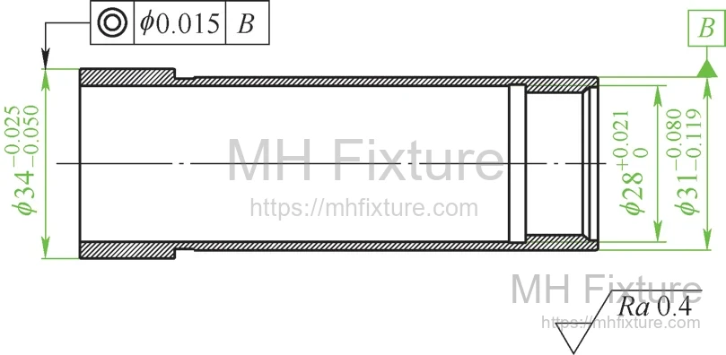
Due to the low structural rigidity, the workpiece is highly sensitive to external forces. The deformation mechanism is primarily driven by three factors:
- Clamping Deformation: Elastic deformation caused by radial chuck pressure.
- Thermal Distortion: Expansion due to grinding heat accumulation in the thin wall.
- Process Vibration: Instability caused by the grinding wheel interface.
2. Process Optimization: Internal Grinding Strategy
The first stage of the process involves grinding the internal bore. Standard 3-jaw self-centering chucks are unsuitable as the point-contact pressure distorts the thin wall into a triangular (tri-lobed) shape.
To resolve this, the clamping method must be upgraded to a Full-Contact Soft Jaw system.
2.1 Limitations of Sleeve Bushings
A common but flawed approach involves placing a thick-walled split bushing over the part before clamping. This method is unreliable for high-precision grinding:
- Over-clamping: Transmits deformation through the bushing to the part.
- Under-clamping: Results in workpiece slippage (rotation within the bushing) as grinding feed pressure increases, leading to roundness errors and safety hazards if the part dislodges axially.
2.2 Solution: Custom Bored Soft Jaws
The optimal solution involves modifying a standard self-centering chuck.
- Fabrication: Weld mild steel or copper segments to the standard master jaws.
- Pre-loading: Tighten the chuck to the minimum clamping diameter state.
- In-situ Boring: Bore the soft jaws to the exact OD dimension of the piston (minus the grinding allowance).
- Result: This creates a near 360-degree surface contact area. When clamped, the force is distributed evenly across the circumference, virtually eliminating radial deformation during the internal grinding operation.
3. Process Optimization: External Grinding Strategy
For the subsequent OD grinding, the process priority shifts to maintaining concentricity with the previously ground bore. The preferred fixturing method is a Tapered Mandrel (utilizing the Morse taper principle).
3.1 Mandrel Design Parameters
- Surface Quality: The mandrel must be ground to Ra < 0.4μm with a roundness < 0.03μm.
- Sizing: The major diameter of the tapered section must be calculated based on the piston's bore diameter plus the allowable elastic expansion limit.
3.2 Managing Interference Fit and Expansion
The critical variable in this setup is the Expansion Quantity—the increase in the workpiece OD caused by the interference fit with the mandrel. The interference force must be sufficient to generate friction torque greater than the grinding torque, yet low enough to keep deformation within the elastic limit.
Standardized Measurement Procedure:
- Initial Position: Place the part on the mandrel until light resistance is felt. Measure the initial OD (average of 3 measurements).
- Clamped Position: Apply axial force to seat the mandrel (creating the interference fit). Measure the expanded OD (average of 3 measurements).
- Calculation: The difference defines the Expansion Quantity. This data is used to offset the final grinding target dimension. Upon removal from the mandrel, the part will "spring back" to the correct specification.
4. Abrasive Selection: Grinding Wheel Specifications
Wheel selection is critical for specific stainless steel grades (e.g., 1Cr17Ni2, 00Cr13Ni8TiNbAl). These materials are characterized by high toughness, high strength, and poor thermal conductivity.
- White Fused Alumina (Corundum): Not recommended. The grains wear too quickly, causing the wheel to lose geometry (developing a taper). This results in "barrel" distortion in bores or "saddle" distortion on ODs.
- Microcrystalline Corundum: Not recommended. While tough, the grains do not self-sharpen easily. This leads to increased grinding forces and heat generation, exacerbating thermal deformation in thin-walled parts.
- Recommended: Green Silicon Carbide (GC):
- Properties: High hardness, high brittleness, sharp cutting edges, and excellent thermal conductivity.
- Advantage: The abrasive grains micro-fracture (self-sharpen) efficiently, keeping the cutting action cool and sharp. This minimizes normal forces and heat input, preserving the dimensional stability of the thin-walled piston.
5. Machining Parameters and Vibration Control
To minimize thermal distortion, the relationship between wheel speed and workpiece speed must be optimized.
- Wheel Surface Speed: 35–50 m/s.
- Workpiece Spindle Speed: 3500 ± 500 r/min.
- Cutting Speed: 60–100 m/min.
Thermal Management: Internal grinding generates significant heat due to the large contact arc between the small wheel and the bore wall. If the spindle speed exceeds the recommended range, vibration increases and the abrasive grains detach prematurely. This generates excessive heat, leading to inconsistent dimensions and severe geometric errors (drum/taper shapes). Sufficient coolant flow is mandatory to prevent thermal expansion during the cut.
6. Process Data Analysis: Expansion vs. Deformation
Controlling the depth of mandrel insertion is key to balancing holding power against geometric deformation. The following data compares the behavior of two piston models (7000-01A and 4002) under varying mandrel insertion depths.
Table 1: Expansion & Deformation Data - Piston Model 7000-01A
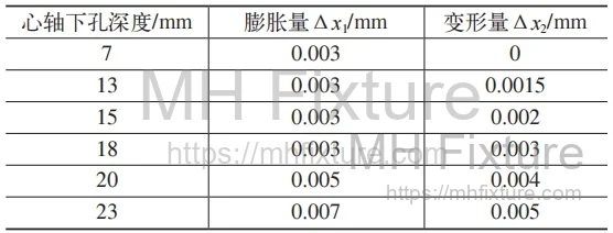
Table 2: Expansion & Deformation Data - Piston Model 4002

Analysis of Data
- Model 7000-01A: With a thicker wall (4mm), deformation is relatively controlled. However, shallow insertion (10mm) risks slippage or vibration at the tail end of the 117mm length, potentially affecting coaxiality.
- Model 4002: With a thinner wall (3mm), this part is highly sensitive. At an insertion depth of 22mm, the deformation (0.015mm) consumes the entire tolerance budget. If processed at this depth, the part will likely be out of tolerance upon removal from the mandrel (elliptical recovery).
Operational Best Practice: Operators must select an intermediate insertion depth (e.g., 14-16mm for Model 4002). This balances the need for sufficient friction torque (to prevent part rotation/slippage) with the requirement to minimize elastic expansion errors.
7. Conclusion
Achieving sub-micron precision on thin-walled stainless steel pistons requires a holistic engineering approach rather than simple parameter adjustment. By transitioning to full-contact soft jaws for internal operations and utilizing precision tapered mandrels with controlled interference for external operations, manufacturers can stabilize the workpiece geometry.
Furthermore, selecting Green Silicon Carbide (GC) abrasives and adhering to strict speed ratios ensures that thermal inputs remain negligible. This systematic process control guarantees that critical tolerances—specifically coaxiality and cylindricity—are consistently met in serial production.